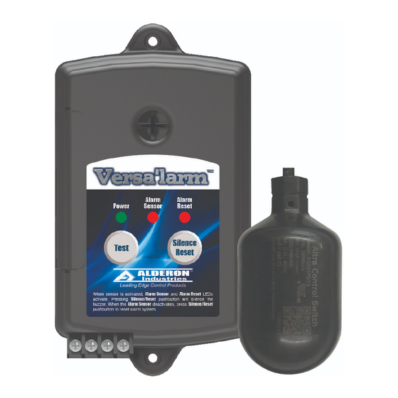
Alderon Industries Wireless Versa'larm VA01B Kullanım, Bakım ve Kurulum Kılavuzu - Sayfa 6
Güvenlik Sistemi Alderon Industries Wireless Versa'larm VA01B için çevrimiçi göz atın veya pdf Kullanım, Bakım ve Kurulum Kılavuzu indirin. Alderon Industries Wireless Versa'larm VA01B 6 sayfaları. 1-zone alarm

Wireless Versa'larm
1-Zone Alarm - Model VA01B
Part Numbers - 7991 and 7992
Operation, Maintenance and Installation Manual
Installation of the Alarm Panel and Wireless Receiver Continued
5. If connecting to an existing alarm security system or building automation system (BAS), leave Terminals "+" and "-" open
and use 18 gauge 2-conductor wire to connect the existing product to Terminals 1A and 1B (Fig. 15). When connected,
replace the access cover and pull wire(s) through the knockout(s) on the access cover (see step 6). The alarm panel is
factory wired with knockout for wireless receiver, use additional knockouts for auxiliary contacts. CATUION! - Route all wires
away from sharp objects and internal components when installing wires.
AUXILIARY CONTACTS:
Terminals "+" and "-"
"+" Not Used
"-" Factory Wired (green)
Terminals 1A and 1B
Normally Open
Class 2, 24 VDC/VAC (50/60 Hz)
100 Milliamps Maximum
Terminals 2A and 2B
2A Factory Wired (black/red)
2B Factory Wired (red/red)
Note: The auxiliary contacts 1A and 1B of the alarm panel are Normally Open only.
6. After the access cover has been removed from the alarm panel (Fig. 16), use a needle nose pliers (not included) to
remove the desired "break away tabs" from the access cover, lightly pull and twist off tab(s) (Fig. 17). Replace the access
cover and run wire(s) through the knockout(s) (Fig. 18).
(Fig. 16)
Testing and Maintenance
1. Plug the alarm panel power supply into a 120 VAC, 50/60 Hz standard wall outlet and the green "Power" LED should
illuminate. Test by pressing and holding the "Alarm Test" pushbutton or activating the "Signaling Device" (float switch). The
buzzer should annunciate and the alarm LED should illuminate. Press the "Alarm Silence" pushbutton and the buzzer
should silence while the alarm LED remains on. After you remove pressure from the "Alarm Test" pushbutton or deactivate
the "Signaling Device", the "Auto Reset" feature reactivates the alarm panel for the next alarm cycle. Test product weekly to
ensure system intergrity. Refer to step-by-step testing instructions on page 2 for further details.
Transmitter Maintenance: The transmitter is a waterproof unit that comes with an internal lithum battery (BWA-BATT-006) which has
an approximate battery life of 5 years under normal operating conditions. Consult the factory for ordering a replacement battery.
Alarm Systems
Control Panels
Alderon Industries - Hawley, MN | 218.483.3034 | [email protected] | alderonind.com
™
(Fig. 17)
Float Switches
Leak Detection Systems
(Fig. 15)
+ -
1A
1B 2A 2B
+ -
1A 1B
(Fig. 18)
Field Wired Knockout
(separate from receiver knockout)
P/N: 101985
2A 2B
Wireless Receiver
Knockout (pre-installed)
Page 6 of 6
