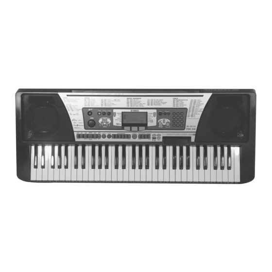
Yamaha PortaTone PSR-350 Servis Kılavuzu - Sayfa 9
Müzik Enstrümanı Yamaha PortaTone PSR-350 için çevrimiçi göz atın veya pdf Servis Kılavuzu indirin. Yamaha PortaTone PSR-350 34 sayfaları.

DISASSEMBLY PROCEDURE
1.
Lower Case Assembly
(Time required : About 5 min.)
1-1.
Remove the fourteen (14) screws marked [270A] and the four (4) screws marked [280A].
The lower case assembly can then be removed. (Fig. 1)
[270A]
[280A]
2.
Spring Terminal
(Time required : About 10 min.)
2-1.
Remove the lower case assembly. (See procedure 1)
2-2.
Remove the BAT connector assembly (red/black)
soldered to the spring terminal (+)/(-). (Fig. 2)
2-3.
Remove the battery cover assembly. (Fig. 1)
2-4.
Remove the spring terminal by releasing hooks (2
locations for each). (Fig. 3)
BAT Connector
Lower Case
Assembly (Black)
Assembly
(Fig. 2)
Hook
(Fig. 3)
Battery Cover Assembly
[270A]
[270A] : Bind Head Tapping Screw-P
[280A] : Bind Head Tapping Screw-P
BAT Connector
Assembly (Red)
Hook
Spring Terminal
[270A]
Lower Case Assembly
[270A]
3.0X12 MFZN2Y
(EP600300)
3.0X25 MFZN2Y
(VK228100)
(Fig. 1)
3.
DM Circuit Board, Shield Box U and L
(Time required : About 10 min.)
3-1.
Remove the lower case assembly. (See procedure 1)
3-2.
Remove the two (2) screws marked [270B] and
the thirteen (13) screws marked [290]. The shield
box U and the DM circuit board can then be
removed. (Fig. 4)
3-3.
Remove the three (3) screws marked [260A]. The
shield box L can then be removed. (Fig. 4)
4.
Floppy Disk Drive Assembly
(Time required : About 10 min.)
4-1.
Remove the lower case assembly. (See procedure 1)
4-2.
Remove the DM circuit board and the shield box
U and L. (See procedure 3)
4-3.
Remove the four (4) screws marked [300]. The
floppy disk assembly can then be removed. (Fig. 5)
5.
AM Circuit Board
(Time required : About 10 min.)
5-1.
Remove the lower case assembly. (See procedure 1)
5-2.
Remove the seven (7) screws marked [260B]. The
AM circuit board can then be removed. (Fig. 5)
PSR-350
[280A]
[270A]
[270A]
9
