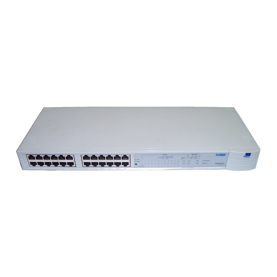
3Com SuperStack II Kullanıcı Kılavuzu - Sayfa 3
Ağ Donanımı 3Com SuperStack II için çevrimiçi göz atın veya pdf Kullanıcı Kılavuzu indirin. 3Com SuperStack II 9 sayfaları. Switch matrix module
Ayrıca 3Com SuperStack II için: Kullanıcı Kılavuzu (4 sayfalar), Kullanıcı Kılavuzu (2 sayfalar), Ek Sayfa (1 sayfalar), Önemli Bilgiler (2 sayfalar), Kullanıcı Kılavuzu (6 sayfalar)

I
NTRODUCTION
®
The SuperStack
II Baseline Switch is a flexible unmanaged switch
that is very easy to use. It can be used to help build a small network
or expand a larger, more established network.
The Baseline Switch has 12 dedicated RJ45 10BASE-T ports on the
front panel and two RJ45 10/100 ports (ports 13 and 14) on the rear
panel (which can both be either 10BASE-T or 100BASE-TX).
The Baseline Switch is suited for office use where it can be free
standing, wall mounted, or rack mounted (in a wiring closet or
equipment room). A mounting kit is supplied.
The unit can be powered either from the AC mains supply, or
through an optional 3Com SuperStack II Advanced Redundant Power
System. Contact your supplier for details.
The Baseline Switch comes with:
3
One power cord for use with the Baseline Switch
3
Four standard height and two reduced height self-adhesive
rubber pads
3
Mounting kit
3
A Warranty Registration card for you to fill in and return
Switching
When a network of repeater hubs is in operation, any information
that is sent by the workstations is passed around the whole network
(regardless of the destination of the information) which results in a
lot of unnecessary traffic that can slow it down. The Baseline Switch
solves this problem because it 'listens' to the network and
automatically learns what workstations and network equipment can
be reached through its ports. It can then selectively pass on any
information by transmitting the traffic to the relevant port only
(instead of all ports like a repeater hub). This operation is called
switching.
The Baseline Switch effectively segments your network, localizing the
network traffic and passing on traffic as necessary. If you have
workstations that communicate frequently in the same part of the
network, traffic between them is not passed to the remainder of the
network, reducing the load.
Connecting 10BASE-T and 100BASE-TX
The 10/100 ports allow you to connect 100BASE-TX networks or
workstations to the Baseline Switch. This means that if you have
both 10BASE-T and 100BASE-TX networks, you can connect them so
that all your workstations can communicate.
Alternatively, if you have 10BASE-T and want to improve
performance by introducing 100BASE-TX, the Baseline Switch
protects your investment because it maintains 10BASE-T connections
to your original network equipment.
H
OW TO
Numbered elements in this diagram refer to numbered sections in the text.
U
B
SE THE
ASELINE
2
Network Connections
The Baseline Switch is ready to use, and can be used stand-alone or
linked with other units, for example repeater hubs.
All ports on the Baseline Switch have full duplex auto-negotiation.
Full duplex operation allows information to be transmitted and
received simultaneously and, in effect, doubles the potential
throughput of a link. If the device connected to a port supports
auto-negotiation, the port operates in full duplex mode. Otherwise
the port operates in half duplex mode.
CAUTION: The equipment that is connected to the Baseline
Switch must not be set up to operate in full duplex. Set it
up to operate as auto-negotiate or half duplex.
Connecting 10BASE-T (Ethernet) Equipment
You can connect 10BASE-T units or DTE (workstations or other
equipment) to any ports on the Baseline Switch. To connect your
equipment, use 10BASE-T Category 3, 4 or 5 unshielded 100 Ohm
TP or shielded (screened) 150 Ohm TP cable.
Category 5 cable must be used with this product in
i
structured wiring environments. This will ensure correct
operation of all ports at 10Mbps or 100Mbps.
Connect one end of the TP (twisted pair) cable to the RJ45 port on
the Baseline Switch and the other end to the appropriate RJ45 port
on the unit or DTE.
To remain within IEEE 802.3 10BASE-T rules, the maximum length of
cable between the Baseline Switch and any DTE should not be
greater than 100m (328ft). If you are connecting DTE to the Baseline
Switch through a series of repeaters, ensure that there are no more
than four repeaters between the Baseline Switch and the DTE.
Connecting 100BASE-TX (Fast Ethernet) Equipment
You can connect 100BASE-TX units or DTE to ports 13 and 14 on
the Baseline Switch. To connect your equipment, use 100BASE-TX
Category 5 unshielded 100 Ohm TP or shielded (screened) 150 Ohm
TP cable.
Connect one end of the TP (twisted pair) cable to the RJ45 port on
the Baseline Switch and the other end to the appropriate RJ45 port
on the unit or DTE.
To remain within IEEE 802.3 100BASE-TX rules, the maximum length
of cable between the Baseline Switch and any DTE should not be
greater than 100m (328ft). If you are connecting DTE to the Baseline
Switch through a series of repeaters, ensure that there are no more
than two repeaters between the Baseline Switch and the DTE, and
that the total cable length does not exceed 205m (672.4ft).
S
WITCH
