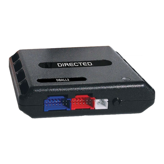
Directed DBALL Kurulum Kılavuzu - Sayfa 10
Otomobil Aksesuarları Directed DBALL için çevrimiçi göz atın veya pdf Kurulum Kılavuzu indirin. Directed DBALL 14 sayfaları.

Platform: DBALL/DBALL2
Firmware:
CHRYSLER6 Range Extender Ready (RXT) Installation
LED Diagnostics & Troubleshooting
LED
Status
Module Programming
Off
Off
Solid
Solid red
red
Green &
Green & Red
red
Flashes
Flashes green
green
Flashes orange
Flashes orange
slowly
slowly
Solid green then
Solid green
then orange
orange for 3 secs.
x 3 secs
Solid orange for 3
Solid orange x
3 secs
seconds.
Solid green x
Solid green for 3
3 secs
seconds
Module Programming - Error codes
Flashes red
Flashes red x 2
x 2
Flashes red
Flashes red x 3
x 3
External module synchronization
Flashes red,
Flashes red, red
red & orange
x 10 secs
then orange, x 10
Active Ground While Running
Flashes
Flashes green
green
Flashes red &
Flashes
red &
orange
orange
Flashes
Flashes green
green
quickly
quickly
D2D and W2W Commands
Flashes
Flashes orange x 1
orange x 1
Flashes
Flashes orange x 2
orange x 2
Description
Module has no power.
Waiting to begin the
programming sequence.
Initialization failed.
Module is programming.
Ready for Key2GO programming.
Bypass was skipped.
Module was successfully
programmed without bypass.
Module was successfully
programmed.
CAN C not detected.
Bypass data not detected.
OBDII feature not supported.
GROUND OUT ON (GWR)
command received.
IGNITION ON command received.
START ON command received.
LOCK command received.
UNLOCK command received.
Go to the next page to see the rest of the LED Diagnostics & Troubleshooting.
Troubleshooting
Make sure the D2D harness is connected or that the 12
Volt is present between the red and balck wires. If the
12 Volt is present, the module be be defective.
Check if the ignition input is properly connected.
If a second attempt fails after a complete Hard Reset,
connect the module to Directechs.com and call Tech
Support with the module ID in hand.
Make sure that the bypass connections are correct (see
wiring diagram).
Normal operation.
Normal operation.
Normal operation.
Normal operation.
Check the CAN connections
Check the bypass line connection. If more than one wire
is used, make sure they are not inverted. Start vehicle
using the key to confirm the OEM equipment is still
operational.
Diagnostic data bus not detected. Some features are
not supported by SmartStart. This can be caused by
missing wire connections or module hardware limitation.
Refer to the wiring installation section to check the
connections.
Otherwise, the Ground While Running (status) signal
was lost or was never received by the module.
Commands can come from RF, D2D or W2W.
Otherwise, the ignition signal was not received by the
module. In a W2W install, it will show only if the ignition
input wire is used.
Otherwise, the start signal was not received by the
module. In a W2W install, it will show only if the ignition
input wire is used.
If the bypass module fails to flash, it means the module
did not receive the signal.
Rev.: 20150827
Page 10
© 2015 Directed. All rights reserved.
