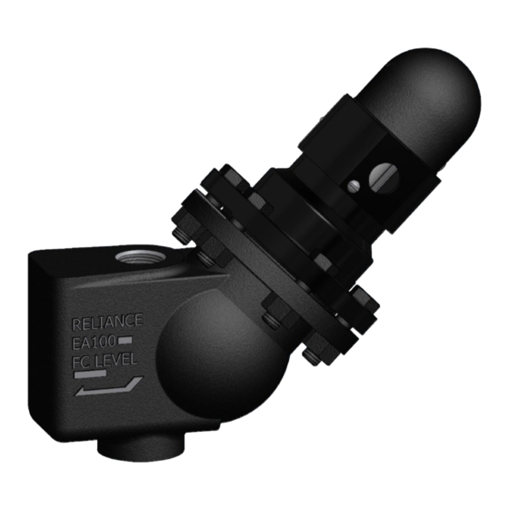
Clark-Reliance Levalarm EA100SW Kurulum ve Çalıştırma Talimatları - Sayfa 8
Endüstriyel Ekipmanlar Clark-Reliance Levalarm EA100SW için çevrimiçi göz atın veya pdf Kurulum ve Çalıştırma Talimatları indirin. Clark-Reliance Levalarm EA100SW 10 sayfaları.

Caution: Before proceeding, follow any and all plant lock out - tag out procedures required. All
installation steps should be performed by a qualified technician and should be executed in
accordance with all applicable national and local codes.
Symptom
1) Float is stuck in the "up" position"
Possible remedies:
1. Conduct a blow down, to ensure there is no water trapped in the unit.
2. Inspect the internal portion of the Levalarm Chamber
a. Isolate the Levalarm and make sure there is no pressure in the unit.
b. Remove the flange head assembly
c. Remove the stainless steel cotter pin(s) that hold the axle pin for the float rod in
d. Remove, inspect, and clean the magnet, if needed.
e. Examine inside the opening of the magnet tube with a light to make sure there is
3. Reassemble the unit. Be sure to use stainless steel cotter pins (if not reusing the
original ones) on the float rod axle pin. Reinstall the Switch head assembly onto the
body with a new C1-3 gasket and apply a Teflon based sealant to both sides of the
gasket. Lubricate the bolts with a Nickel based high temperature lubricant and torque
the 4 or 6 bolts to 70 FT-LB, in 1/3 increments.
4. Test the unit for proper functioning
a. To test the switch assembly, set the unit in a vise and make sure that the switch
b. Attach an ohm meter to the common and normally open switch contact and
c. Then, move the ohm meter terminal from the normally open terminal to the
5. If the unit fails to test properly, contact Clark-Reliance for further instructions to adjust
the switch mechanism or to obtain authorization to return the unit for factory inspection.
If the switch tests OK, return unit to service.
TROUBLESHOOTING THE EA100 SERIES LEVALARM
place. Inspect the pivot point where the pivot rod is inserted. Make sure that the
hole in the magnet tube is not elongated. This can cause the float assembly to
hang up.
no debris trapped inside the tube.
housing is on the same 45 degree angle as if it were mounted on the boiler
piping.
manually move the float up and down and verify the switch operates on both
directions. The meter should indicate continuity only when the switch is operated
in the closed position.
normally closed terminal and repeat the test. The meter should indicate an open
circuit only when the switch is in the open position.
Probable Cause
a) Contamination on magnet
b) Magnet too strong
c) Pivot Rod wear or contamination
