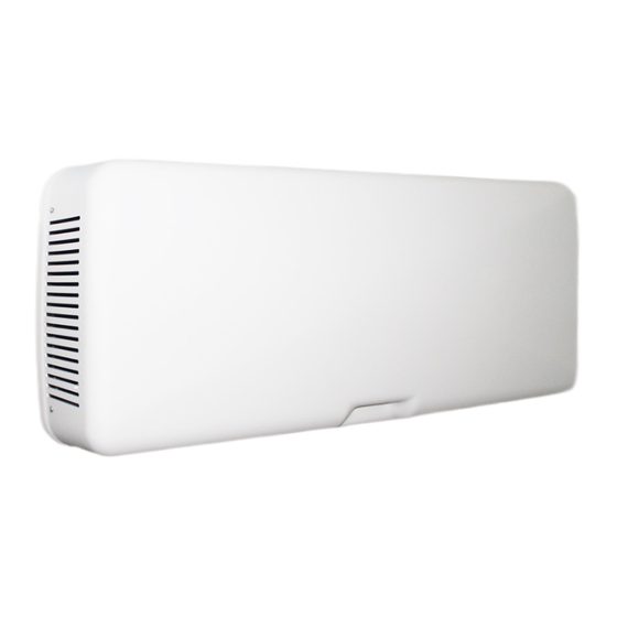
aerauliqa QR100M Kurulum Kılavuzu - Sayfa 5
Isıtma Sistemi aerauliqa QR100M için çevrimiçi göz atın veya pdf Kurulum Kılavuzu indirin. aerauliqa QR100M 16 sayfaları. Heat recovery ventilation unit

5.3 Installation
The unit must be installed in the following position.
It is important that the unit is completely flat in order for the condensation drainage to work properly.
Fig. 5.a,b,c
Fig. 5.d
Spirit level
Fig. 5.h
5.a Prepare the surface where the unit is to be mounted. Make sure that the surface is flat, leveled and that it supports the weight of the unit. Perform the
installation in accordance with local rules and regulations.
5.b Use the supplied template to mark the right positions of the air intake and exhaust holes, of the fixing screws of the mounting bracket, of the hole for the
electrical cable and of the condensation drains. Make sure that the template is at spirit level.
5.c Drill the holes in the external wall.
5.d Use the appropriate fasteners (not supplied) to fix safely the mounting bracket on the wall: make sure that the bracket is properly installed to support the
unit weight.
5.e Fix the spigots in the wall safely.
5.f Hook the main body of the unit at the bracket, making sure that the two holes on the rear side of the casing are in line with the spigots fixed at the wall.
5.g Fix the main body to the wall by means of screws (not supplied).
5.h Make sure that the unit is completely flat once installed.
5.i Connect the condensation elbow(s) to the drainage hole(s) at the bottom of the casing: in case one hole is not used, close and seal it with the supplied plug.
Make sure of water and air tightness of all connections. It is necessary to use a U-bend (or similar) in the condensation drainage pipe. Connect the unit
electrically according to point 5.5. Check that it starts up correctly.
5.j Fix the ABS cover to the main body by means of the supplied screws.
Fig. 5.e
H
Fig. 5.i
Fig. 5.f
H=min. 60mm
Fig. 5.g
H
Fig. 5.j
5
