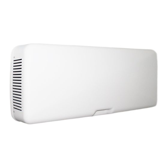
aerauliqa QR100M Kurulum Kılavuzu - Sayfa 8
Isıtma Sistemi aerauliqa QR100M için çevrimiçi göz atın veya pdf Kurulum Kılavuzu indirin. aerauliqa QR100M 16 sayfaları. Heat recovery ventilation unit

6 commIssIoNINg
6.1 Setting Fan speed
The speed of the unit can be adjusted during installation according to required ventilation rate.
Figure 6.a below shows performance curves (for supply air and extract air) at different settings of the 0-10V signal to the motors. Airflow and consumption
refer to the 2 motors.
Table 6.b indicates the efficiency of the heat exchanger and of the condensation produced in different climatic conditions, to help the installer or the designer
of the ventilation system to decide if to connect one or both condensation drainages.
High production of condensation is the direct consequence of a high efficiency level as well as of the humidity rate.
480
400
320
240
160
D
80
C
B
I
A
0
0
20
Fig. 6.a Intake curve according to Reg. 1253/2014 (ErP).
Product tested without filter F7.
EXTERNAL
ESTERNO
T
°C
-18
-18
-18
-10
-10
-10
0
0
0
10
10
10
35
35
35
40
40
40
Fig. 6.b Thermal efficiency of the heat exchanger and average production of condensation water. Data supplied by the manufacturer of the heat exchanger.
The heat exchanger is tested at the University of Luzern (Hochschule Lezern).
8
G
F
E
IV
III
II
40
60
Airflow - m
/h
3
Working point
I
II
III
IV
V
VI
(1) Termal efficiency of the unit.
INTERNAL
INTERNO
R. H.
T
R. H.
%
°C
%
60
20
30
70
20
40
80
20
50
60
20
30
70
20
40
80
20
50
50
20
30
60
20
40
70
20
50
50
20
40
60
20
50
70
20
60
60
26
50
70
26
55
80
26
60
60
26
50
70
26
55
80
26
60
VI
V
80
100
120
W
m
/h
sPI (W/m
3
8,3
21
0,395
13
37
0,351
21,8
54
0,404
33,1
66
0,5015
50,2
82
0,6122
57,5
93
0,6183
25 m³/h
50 m³/h
H
O
H
ᶯ
ᶯ
2
%
kg/h
%
kg/h
96,6
0,08
93,5
0,15
97
0,11
94,3
0,21
97,4
0,14
95,1
0,28
96,4
0,05
93,1
0,09
96,9
0,08
94,1
0,15
97,4
0,11
94,9
0,21
95,6
0,01
91,3
96,3
0,03
92,8
0,05
96,9
0,05
94,1
0,1
95,4
0
91,3
95,4
0
91,3
96,1
0,01
92,3
0,02
95,5
0
91,4
96,9
0,02
93,9
0,04
98,1
0,05
96,4
0,09
97,1
0,04
94,4
0,08
98,1
0,07
96,3
0,14
98,8
0,1
97,6
0,19
TrimmEr V1- V2
D
C
B
A
speed
curve
%
A (min)
24
B
30
C
43
D
61
E
75
F
93
G (max)
100
ɳt %
/h)
(1)
3
93
91
89
87
85
84
75 m³/h
100 m³/h
O
H
O
ᶯ
ᶯ
2
2
%
kg/h
%
90,6
0,21
88
91,9
0,31
89,6
92,9
0,41
91
89,9
0,13
87
91,4
0,22
89
92,7
0,3
90,6
0
87,5
0
84,1
89,5
0,07
86,3
91,4
0,14
88,9
0
87,5
0
84,1
0
87,5
0
84,1
88,6
0,02
84,9
0
87,7
0
84,3
91
0,05
88,1
94,7
0,13
93,1
91,7
0,1
89
94,5
0,2
92,9
96,6
0,29
95,6
E
F
G
W
m
/h
3
max
max
8
19
9
24
13
40
22
57
34
71
51
88
58
100
H
O
2
kg/h
0,27
0,4
0,53
0,16
0,28
0,39
0
0,08
0,18
0
0
0,01
0
0,06
0,17
0,12
0,26
0,37
