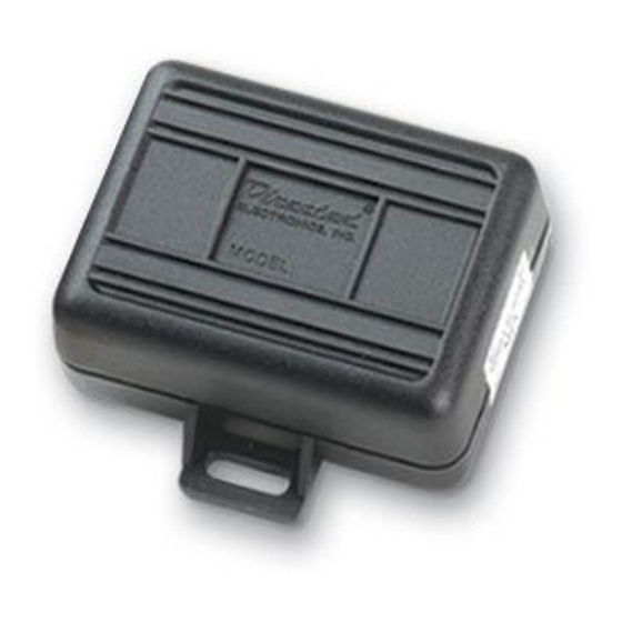
Directed Electronics 555X Manuel
Araba Alarmı Directed Electronics 555X için çevrimiçi göz atın veya pdf Manuel indirin. Directed Electronics 555X 2 sayfaları. Lexus immobilizer bypass module

Models
Lexus GS300: 2002
Product Description
The Lexus Immobilizer anti-theft system uses a low-power
transponder mounted in the head of the ignition key. When the
vehicle is started, the Key Cylinder Module converts the transpon-
der signal and sends a secure, coded signal to the Engine Control
Module. If the signal to the Engine Control Module is correct, the
vehicle will start.
The 555X uses a unique autoprogram sequence to learn the secure
code from the Key Cylinder Module and repeats it when remote start
is activated, eliminating the need to leave a key in the vehicle.
The 555X Lexus Immobilizer Bypass Module integrates into the
wiring for the Lexus immobilizer anti-theft system to allow remote
start capability, while still allowing normal function of the factory
immobilizer anti-theft system.
WARNING! It is recommended that the 555X Immobilizer
Bypass Module only be installed by an authorized Directed
dealer. Attempting installation without the proper tools and
training can result in damage to the vehicle electronics.
Pre-Installation Test
IMPORTANT! Wire connections from the 555X to the Lexus
immobilizer wires should be done AFTER all remote start
connections are completed and the following test is suc-
cessful.
After completing all remote start wiring connections, insert the
vehicle key into the ignition switch. Do NOT turn the ignition on.
Activate the remote start.
If the vehicle remote starts, proceed with the 555X installation. If
the vehicle fails to start, check all ignition and tachometer con-
nections and retest. Do NOT proceed with 555X installation until
this test is successful.
555X Lexus Immobilizer
Bypass Module
A successful test verifies that all ignition and tachometer con-
nections are correct. This will eliminate the remote start as the
cause of a failure to start after completing the 555X installation.
Installation Instructions
1.
Remove steering column shroud to gain access to the wire
harnesses at the rear of the ignition switch.
2.
Locate the appropriate wires exiting the ignition switch and
immobilizer receiver. The wire colors are listed in the
Application Guide.
3.
Wire the 555X as shown in the wiring diagram.
Wire Connection Guide
GREEN: Connect this wire to the (-) key sense wire at the
ignition cylinder. The key sense wire rests at ground when the
key is inserted into the ignition switch.
BLACK: Connect this wire to a quality chassis ground (prefer-
ably scraped sheet metal) separate from other component
ground locations.
BLUE: Connect this wire to the BLUE status output of the
remote start. It must see ground during remote start.
RED: Connect this wire to a constant (+)12 volt source.
YELLOW: Locate the Data wire listed in the Application Guide
and cut it. Connect this wire to the end of the Data wire that
is coming from the ignition switch.
YELLOW/BLACK: Connect this wire to the end of the Data wire
that goes toward the ECM side.
IMPORTANT! Signals on the immobilizer wires are Data,
not voltage. They can't be tested with conventional test
equipment. All connections should be made using solder
and tape to avoid any signal loss due to resistance in the
connections. Quick connects are unacceptable!
VIOLET: Connect this wire to the keyside of the clock wire.
VIOLET/BLACK: Connect this wire to the clock wire's ECM side.
BROWN: Connect this wire to the Synch wire listed in the
Application Guide.
© 2002 Directed Electronics, Inc. Vista, CA
N555X 10/02
