Alemite 8549-C Servis Kılavuzu - Sayfa 7
Su Pompası Alemite 8549-C için çevrimiçi göz atın veya pdf Servis Kılavuzu indirin. Alemite 8549-C 13 sayfaları.
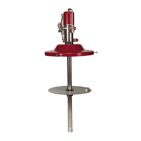
High Pressure Lubricant Pump
IMPORTANT: Prior to performing any maintenance procedure, the
following safety precautions must be observed. Personal in}ury
may occur.
WARNING
Do not use halogenated hydrocarbon solvents such
as methylene chloride or 1,1,1-trichloroethane in this pump. An
explosion can result within an enclosed device capable of con-
taining pressure when aluminum and/or zinc-plated parts in the
pump come in contact with halogenated hydrocarbon solvents.
Release all pressure within the system prior to performing any
overhaul procedure.
• Disconnect the air supply line from the pump motor.
• Into an appropriate container, operate the control valve to
discharge remaining pressure within the system.
Never point a control valve at any portion of your body or anoth-
er person. Accidental discharge of pressure and/or material can
result in injury.
Read each step of the instructions carefully. Make sure a prop-
er understanding is achieved before proceeding.
Overhaul
NOTE: Refer to Figure 2 for component identification on all
overhaul procedures.
Disassembly
1 Secure the pump assembly in a soft-jaw vise at Adapter (13).
NOTE: Secure model 8549-B1 at Bung Adapter (44).
2 Extend Rod (37) to end of Primer Body (43).
• Apply air to the motor as necessary.
3 Gently remove Nut (40) from the Rod.
• Use an appropriate size punch in the hole of the Rod to prevent
rotation. See Figure 2.
4 Remove Primer Disc (39) from the Rod.
5 Push the Rod into the Primer Body.
Pump Tube (Outer Components)
6 Rotate the Primer Body.
• Use a large wrench or other suitable tool.
NOTE: The pump tube will break at one of three places. Unscrew
the separated portion from the inner components of the pump tube
assembly.
7 Remove Follower Tube (41) [assembly] from the inner tube
assembly.
8 Unscrew the air motor from Adapter (13).
• Rotate the air motor assembly.
9 Remove O-Ring (12) from the Adapter.
NOTE: If the pump was not leaking at the top of Tube (26), do not
separate the Adapter from the Tube. Components are locked with
Loctite® 222 ™.
10 Unscrew Tube (26) from the Adapter as required.
• Remove Gasket (14).
11 Clamp Retainer (28) horizontally in a soft-jaw vise.
12 Unscrew the Primer Body from Extension (32).
13 Remove O-Ring (42) from the Primer Body.
IMPORTANT: Remove Valve Seat (36) squarely from the Primer
Body. Should the Valve Seat cock during removal, realign and
start again. Gasket (14) may interfere.
14 Remove Valve Seat (36) from the Primer Body.
15 Remove Gasket (14) from the Valve Seat.
16 Unscrew the Extension from the Retainer.
17 Remove Gasket (31) from the Extension.
18 Remove Valve Body (35) from the Extension.
• Remove Stop Washer (33).
19 Remove Seal (34) from the Valve Body.
20 Remove Bearing (30) and Seal (29) from the Retainer.
21 Unscrew Tube (26) from the Retainer.
22 Remove Gasket (14), Bearing (27), and additional Gasket (14)
from the Retainer.
7
SER 8540-B