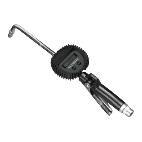
Alemite 3622 Servis Kılavuzu - Sayfa 8
Kontrol Ünitesi Alemite 3622 için çevrimiçi göz atın veya pdf Servis Kılavuzu indirin. Alemite 3622 11 sayfaları. Electronic-metered control valve

SER 3620
Assembly
NOTE: Prior to assembly, certain compo-
nents require lubrication. Refer to Table 2
for details.
Control Valve Handle
NOTE: Refer to Figure 6 for a section
view of the control valve handle assembly.
1. Install Roll Pin (31) into Body (30) as required.
IMPORTANT: Lubricate O-Rings (42)
with grease prior to installation.
2. Install O-Rings (42) onto Cam (43).
3. Install the Cam assembly into the Body.
• Make sure to orient the Cam as shown in Figure 5.
4. Position Lever Assembly (40) onto the tabs of the
Cam.
• Make sure the safety does not interfere with the
Body.
5. Install Screws (41) that secure the Lever Assembly
to the Cam.
• Tighten the Screws securely.
6. Install Seal (33) [blunt end first] onto Push Rod (32).
7. Install Spring Support (35) into the small end of
Compression Spring (36).
8. Install Small Compression Spring (34) onto the
Spring Support.
9. Install the Push Rod and Seal assembly onto the
Spring Support.
10. Install the Compression Spring (with assembled
components) into the Body.
• Make sure the Push Rod seats properly on the
Cam.
11. Install Strainer (37) into the Compression Spring.
12. Install O-Ring (38) onto Swivel Assembly (39).
Item No.
17
O-Ring, 1/2 " ID x 5/8 " OD
42
O-Ring, 1/2 " ID x 11/16 " OD
Revision (11-05)
1-800-548-1191-http://[email protected]
13. Screw the Swivel Assembly into the Body.
Description
Clean Oil
Multi-Purpose Grease
Table 2 Lubricated Components
8
Electronic-Metered Control Valve
NOTE: Swivel Assembly is under Spring pres-
sure during installation.
• Tighten the Swivel Assembly securely.
Transmission Fluid Filter
NOTE: Refer to Figure 5 for component iden-
tification.
1. Install Filter Tube (26) into Body (25).
2. Install O-Ring (28) onto Spring and Adapter Assembly
(29).
3. Install the small button of Stud (27) into the spring of the
Spring and Adapter Assembly.
4. Screw the Spring and Adapter Assembly into the Body.
• Tighten the Spring and Adapter Assembly securely.
Non-Drip Nozzle (Automatic w/ Manual Lock)
NOTE: Refer to Figure 3 for component iden-
tification.
1. Install Gasket (22) into Angle Body (21).
2. Install Washer (23) into Screw Assembly (24).
3. Thread the Screw Assembly into the Angle Body.
• Tighten the Screw Assembly securely.
4. Install O-Ring (17) onto Nozzle (16).
5. Install and seat V-Block (18) [concave first] onto the
pointed end of Stem (19).
6. Install the Stem assembly [point first] into the Nozzle.
7. Install Spring (20) into the Stem.
8. Screw the Nozzle assembly into Angle Body.
• Tighten the Nozzle securely.
Item No.
28
O-Ring, 3/4 " ID x 15/16 " OD
38
O-Ring, 13/16 " ID x 1 " OD
Description
Alemite LLC
