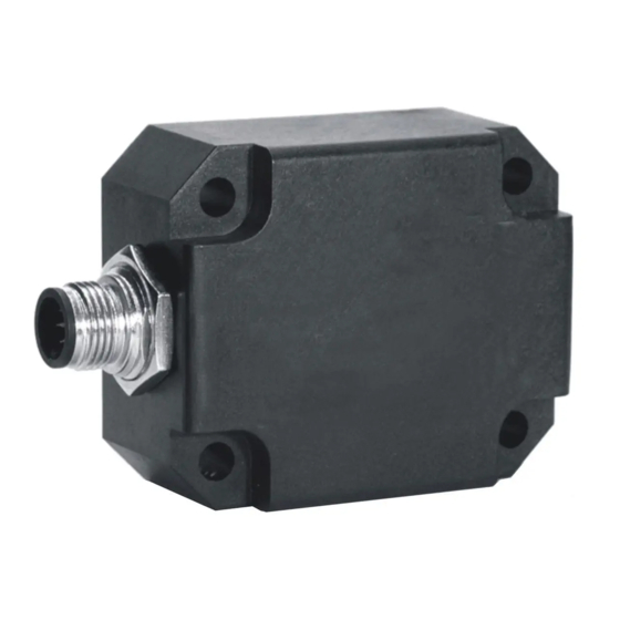
DIS Sensors CAN Kullanıcı Kılavuzu - Sayfa 5
Aksesuarlar DIS Sensors CAN için çevrimiçi göz atın veya pdf Kullanıcı Kılavuzu indirin. DIS Sensors CAN 18 sayfaları. Inclination safety sensor

CAN User Manual
Inclination Safety Sensor
(Type D) V2.0
4
Certification
EC Type examination by:
Name:
DEKRA testing and Certification GmbH
Adress:
Handwerkstraße 15, D-70565, Stuttgart, Germany
Identification Nr.:
0158
EC Type-Examination Certificate no. 4821024.21001
Certificate valid until June 14th 2026
Certified level: SIL CL2 (claim limit 2 according to IEC 62061) & PLd (according to EN ISO 13849)
Architecture: HFT=1 (according to IEC 62061) & CAT3 (according to EN ISO 13849)
5
Inclination sensor explained
An inclinometer measures the angle(s) of the device with respect to earth gravity, using earth gravity vector as
external reference. The inclinometer involved is based on an accelerometer. The acceleration values are used to
calculate the angle(s). The device takes both the static component (100%) and the dynamic component (partial,
depending on frequency and bandwidth-setting) into account. The device will periodically send a CAN message
on the CAN-bus containing the angle(s) in degrees.
6
Safety function
The safety function of the inclinometer sensor is to generate angle information based on acceleration values
(caused by gravitation) measured by a MEMS acceleration sensor chip. Based on this angle information the safety
controller of the application can switch the machine to safe-mode in order to prevent for a dangerous situation.
Example: a crane having a maximum tilt angle of the chassis. If the tilt angle of the chassis exceeds a certain
critical value, the crane will fall over. To prevent for this an inclinometer can be mounted on the chassis,
measuring the X- and Y tilt of the chassis. The safety controller of the application should monitor the X- and Y tilt
angles and should switch the crane to safe-mode as soon as a certain tilt angle for X and/or Y exceeds the limits
for the application. This will significantly reduce the risk of a dangerous situation to happen.
7
Hardware setup
Connection:
Default:
2x 5-pins M12 connector (A-coding), female & male, loop-through.
According to CiA303 V1.8.0
Figure 1: Layout CAN bus connector
Optional:
1x 5-pins M12 connector (A-coding) male only
CAN-Cable with 5-pins M12 connector (A-coding) male
CAN-Cable 5-wire
CAN-bus termination 120Ω
Default:
no CAN-bus termination inside
Optional:
CAN-bus termination inside
Tip: the last CAN-device in the chain should be terminated. For this purpose you can use the
M12 male 5-pin termination resistor' (DIS article number 10217) or the
M12 female 5-pin termination resistor' (DIS article number 10194).
Page 5 of 18
