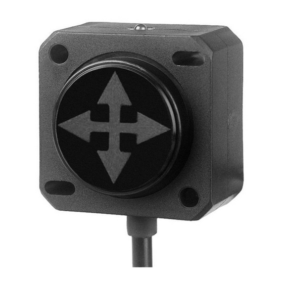
DIS Sensors QG40N Kullanım ve Güvenlik Kılavuzu - Sayfa 2
Aksesuarlar DIS Sensors QG40N için çevrimiçi göz atın veya pdf Kullanım ve Güvenlik Kılavuzu indirin. DIS Sensors QG40N 6 sayfaları. Tilt/acceleration switch (sil1 plc)
Ayrıca DIS Sensors QG40N için: Kullanıcı Kılavuzu (5 sayfalar), Kullanıcı Kılavuzu (15 sayfalar)

QG40N Tilt SIL1 PLc
User Safety Manual v1.3
Introduction
1
This manual is valid for the following safety sensors from DIS-sensors
'QG40N Tiltswitch SIL1 / PLc'
'QG40N Acceleration switch SIL1 / PLc'
Family overview:
•
One housing type:
•
Two different Tilt switch types:
Tiltswitch 1-axis (vertical plane) up to ±170° range, outputs 2x NPN or 2xPNP
Tiltswitch 2-axis (horizontal plane) up to ±80° range, outputs 2x NPN or 2xPNP
(Types available with M12 connector or cable with open ended wires)
Various sensor-settings can be configured in the factory or by the customer using the optional 'QG40N
configurator'
•
Two different Acceleration switch types:
Acceleration switch 2-axis (horizontal plane) up to 8g, outputs 2x NPN or 2xPNP
Acceleration switch 3-axis (omnidirectional) up to 8g, outputs 2x NPN or 2xPNP
(Types available with M12 connector or cable with open ended wires)
Various sensor-settings can be configured in the factory, no 'QG40N configurator' support
Quick Reference Guide
2
•
Safety level: SIL CL 1 / PLc
•
Dual NPN or Dual PNP outputs (200mA continuous, all outputs simultaneously)
•
Zeroing adjustment available via separate input
•
Tiltswitch: User configurable by optional 'QG40N configurator' (switch points, delay-times, filtering)
•
Acceleration switch: No QG40N configurator support
•
Default bandwidth Tilt switch: 0.7Hz, sample rate g-sensor-chip: 3200Hz.
•
Bandwidth Acceleration switch: 1600Hz, sample rate g-sensor-chip: 3200Hz
•
Tiltswitch output filter: adjustable low-pass filter 1
Safety, Installation, use & maintenance
3
•
By ignoring the safety instructions the manufacturer cannot be hold responsible for any damage or hazard.
•
If any damage is noticed the device must be replaced by a new one in order to avoid hazard.
•
Never move the sensor by pulling the cable.
•
The device should only be used in environmental situations covered by the datasheet.
•
As this device is accelerometer-based the sensor is inherent sensitive for accelerations/vibrations. Application
specific testing must be carried out to check whether this sensor will fulfil customer requirements.
•
The family of sensors involved will have a variety of types. Datasheets are available for each specific type.
Customer must select and read the datasheet for the product he is using.
•
The Safety Related Fault Response Time (SRFRT) of this device is defined as the maximum time the sensor will
report a non-safe situation to the outside world, after detecting an internal safety error. The actual value is specified
in the datasheet
•
Configuration of the Tilt switch device like changing Set points, filtering etc. can be done with the optional QG40N
configurator. The customer is responsible to only let authorized / trained personnel do this configuration.
The manufacturer is not responsible for these configuration changes.
•
The sensor should be mounted on a stable flat surface with at least two screws tightened.
•
Customer takes care to only use good quality industrial connectors/cabling to connect the sensor.
•
The proof test interval (mission time) for this sensor is 20 year. After this interval the sensor should be replaced or
checked by comparing the output to a reference sensor, or checked / recalibrated by the manufacturer. This is to
check for any non-detectable faults and/or degradation. This check / recalibration is not included in the price.
•
The calculated MTTFd of the sensor is specified in the datasheet.
•
This sensor does not require any maintenance between proof-test intervals.
page 2 of 6
40x40mm plastic
st
order. Controlled by QG40N configurator
2
