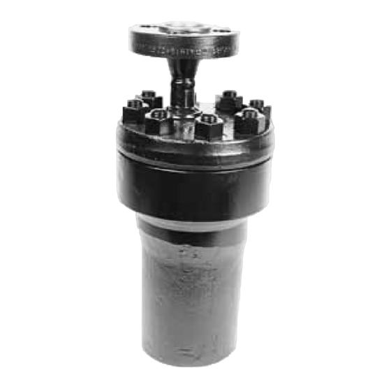
Armstrong FLO-RITE-TEMP 415 Kurulum ve Ayarlama Talimatları - Sayfa 4
Su Isıtıcı Armstrong FLO-RITE-TEMP 415 için çevrimiçi göz atın veya pdf Kurulum ve Ayarlama Talimatları indirin. Armstrong FLO-RITE-TEMP 415 20 sayfaları. Inverted bucket steam traps
Ayrıca Armstrong FLO-RITE-TEMP 415 için: Kurulum ve Ayarlama Talimatları (17 sayfalar), Ürün Açıklaması (4 sayfalar)

Minimum line sizes to drain should be as follows:
model 415 = 3/4", model 535 = 1", model 665 =
1-1/4", model 8120 = 2". Line sizes smaller than
these will not allow sufficient flow for making high
flow settings on the mixing valve.
5.
A water temperature gauge should be installed
directly after the by-pass drain valve. This
thermometer is only used for inital temperature
adjustments of the Flo-Rite-Temp or troubleshooting
the unit. (See Fig. 3-1B)
6.
If a recirculation system is used with a FLO-RITE-
TEMP, a small diverting valve must be piped into the
loop return downstream of the recirculating pump
(See Fig. 3-1C). This device is used to divert
recirculated water back to the heater for reheating if
the temperature of the water drops too low due to no
hot water demand from the system plus piping
radiation losses (See page 9 for operation
explanation). Be sure to pipe in unions and isolation
valves to facilitate diverting valve removal required
when element replacement is needed. A throttling
type valve should be installed in a full return line size
bypass around the diverting valve in order to
balance the flow to the diverting valve. This is
especially needed when recirculating pumps are large
or oversized.
1.
Thread relief valve into the 1/4" NPT port located
on the lower diaphragm half near the spring
chamber. See drawing 4-1.
2.
Tighten with a 3/4" wrench. Warning: Do Not
Over Tighten. Distortion can result causing the
relief valve not to seat.
Note: The discharge of the relief valve is 1/4" FPT and
can be piped over to a drain to prevent the relief
valve discharge from going onto the floor
underneath the Flo-Rite-Temp.
Note: The function of this pressure relief valve is to
relieve any excess pressure on the water side of
the Flo-Rite-Temp resulting from system water
hammer or water expansion pressure due to
water heating. If the problem is severe, water
hammer arrestors should be placed on all
equipment with fast closing water valves.
Expansion tanks should be used for all
expansion pressure problems. The relief set
point of this valve is 165 psig.
Note: The Armstrong Flo-Rite-Temp comes supplied
with a 1/4" NPT water pressure relief valve.
The standard valve has a cracking pressure of
165 psig. Installation instructions (AY-700) are
7.
For a recirculated system, a small constant running
pump should be piped in on the return side of the
loop (See Fig.3-1D). This pump should be sized to
move approximately 10% of the maximum rated gpm
of the FLO-RITE-TEMP in the system with enough
head to overcome the head encountered in the loop.
NOTE: A thermometer should be installed in the
outgoing loop to monitor system temperature
(Fig. 3-1E). A thermometer may also be installed on the
loop return to monitor temperature drop through the loop
or to help troubleshoot the diverting valve (Fig. 3-1D). The
thermometer referred to in point #4 and Fig. 3-1B should
only be used to set the FLO-RITE-TEMP and never used to
monitor system temperature.
NOTE: Expansion tanks should be used in on/off
demand applications where there is a short duration of
time from high flow to no flow of water, i.e., a shut off time
of 10 seconds or less. (See Fig. 3-1F)
Pop-Off Valve
Installation Instructions
supplied with each heater. The valve is a self
relieving and self seating valve which will open
due to thermal expansion or hydrolic shock.
Continuous or intermittent discharge of this
valve while heater is in service could indicate a
system pressure problem. See note for
(Figure 3-1F) expansion tanks on previous page
possible solutions.
Drawing 4-1.
Note: For hard water applications, pipe pop-off
valve into a dirt leg.
4
