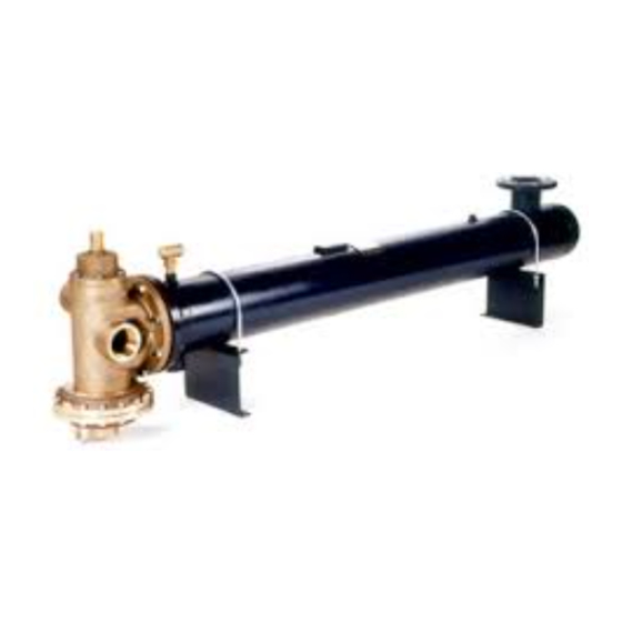
Armstrong FLO-RITE-TEMP 535DW Kurulum ve Ayarlama Talimatları - Sayfa 6
Su Isıtıcı Armstrong FLO-RITE-TEMP 535DW için çevrimiçi göz atın veya pdf Kurulum ve Ayarlama Talimatları indirin. Armstrong FLO-RITE-TEMP 535DW 17 sayfaları. Instantaneous water heater. instructions for single and double wall units
Ayrıca Armstrong FLO-RITE-TEMP 535DW için: Kurulum ve Ayarlama Talimatları (20 sayfalar)

IMPORTANT UNIT START-UP AND
SHUTDOWN PROCEDURES
Its important to remember that water
pressure must ALWAYS be greater than steam
pressure on the unit to avoid boiling the water
in the tubes of the heat exchanger. When
starting up a
FLO-RITE-TEMP it is very
important that the water supply is turned on to
the unit before any steam is turned on. Once the
unit is up and running, the inlet water valve
should never be closed unless the steam is
turned off first. When shutting down a unit you
should always first shut off the steam and then
allow water to run through the unit until it has
cooled and completely condensed all remaining
steam in the heat exchanger before closing off
the supply water to the unit.
ADJUSTING PROCEDURES
All models of FLO-RITE-TEMP's have two
settings which need to be made on initial start-up.
One setting must be made at low flow while the other
is made at high flows. IMPORTANT: Once the
low and high flow adjustments have been made,
the unit generally need not be adjusted again
unless your operating conditions change or a
different set point is desired. A significant drop
in temperature output or capacity is an
indication of a bad diaphragm or that the tube
bundle needs to be cleaned. Do not readjust the
valve unless isolation of the unit from the
system and running water to drain produces
poor temperature control. If capacity is
minimal, check the diaphragm or clean the
bundle but do not readjust the control valve.
START-UP AND ADJUSTING
PROCEDURE FOR MODEL 415
1.
Before turning on the steam to the FLO-RITE-
TEMP, begin by opening the water supply valve
to the unit and checking for water leaks at the
unit or any of the associated piping.
2.
If the unit is connected to a system which has a
recirculation loop and pump, be sure the pump is
turned off and the isolation valve on the leg of
piping going from the diverting valve back to the
inlet of the FLO-RITE-TEMP is closed (this is
the isolation valve downstream of port "B" of the
thermostatic diverting valve). (See Fig. 3-1)
October 31, 2002 @ 3:15 pm
3.
Close the isolation valve on the hot water outlet of
the unit and open full and close several times the
throttling bypass valve to drain to purge all the air
from the FLO-RITE-TEMP. (See Fig. 3-1B).
This process also primes the units lower
diaphragm area with water. Failure to do this
prior to initial adjustment can result in
inaccurate settings and poor results.
4.
Throttle the bypass valve to drain so that a
constant 3 gpm of flow may pass to drain.
5.
Slowly open steam valve or adjust the pressure
reducing valve to allow 2 - 15 psig of steam
pressure on the unit
(CAUTION: always make sure there is water
pressure on the unit before adding steam.
Failure to do this will cause severe
hammering of the unit and possible damage).
6.
Make sure that the steam trap draining the unit is
functioning properly and allow the entire unit to
come up to temperature for at least three to five
minutes while passing the 3 gpm of water flow to
drain before beginning the adjustment of the unit.
7.
Locate the low and high flow adjustments on top
of the mixing valve hidden under the hex bonnet
(see Fig. 7-1). Before beginning adjustments,
check to make sure the high flow adjustment is
fully open. To do this start by pressing down on
the high flow adjustment when water pressure is
present on the unit and there is no water flow
through the unit. This should only depress about
1/8". If it pushes in further, turn the adjustment
stem counter clockwise to open. Check every
turn until there is only 1/8" travel to the high flow
stem when pushed down (Note: with water
pressure on the unit the stem should pop back up
after depressing it). If the high flow adjustment
stem will not depress at all the valve is opened too
far and you must turn the adjustment clockwise
until there is 1/8" travel downward to the stem.
8.
With the unit now isolated from the hot water
system and all flow of water being directed to
drain at 3 gpm, let the temperature stabilize.
9.
Monitor the outlet temperature on the gauge
located in the bypass to drain (see Fig. 3-1B).
Place an adjustable wrench on the flats of the low
flow adjustment (see Fig. 7-1).
Turning clockwise raises the discharge
temperature and counter-clockwise lowers the
discharge temperature. Make the appropriate
adjustment to achieve the desired set point. For
6
