AERF WIRELESSBAND 1.0 Kullanım Kılavuzu
Alıcı AERF WIRELESSBAND 1.0 için çevrimiçi göz atın veya pdf Kullanım Kılavuzu indirin. AERF WIRELESSBAND 1.0 2 sayfaları.

GB
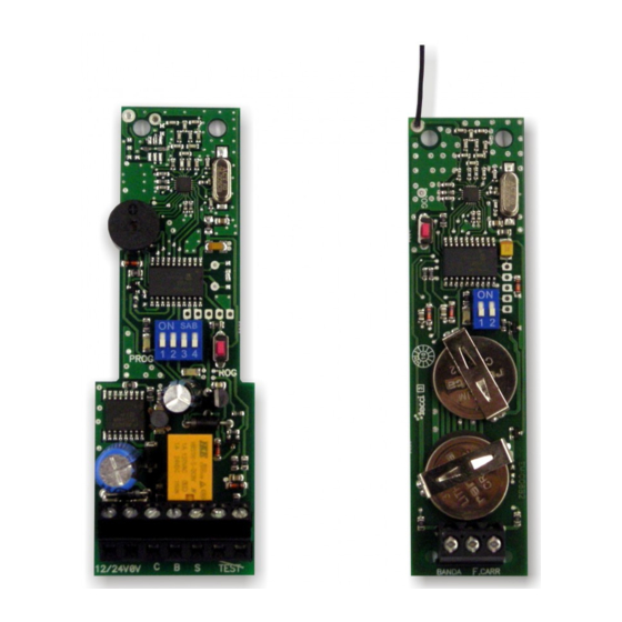
TRANSMITTER
TRANSMITTER
7
6
4
5
3
2
1
1
1- Terminals
2- Battery1 CR2032
3- Battery 2 CR2032
4- LED
5- DIP - Switch
6- Push button
7- Antenna
TECHNICAL SPECIFICATIONS
Receiver suply voltatge
12/24 AC/DC
Transmitter suply voltatge
2x lithium battery 3V DC type CR2032
Receiver memory
14 transmitters
Receiver Output
Relay,micro disconnection 1B
Receiver Power consumption
0.5 W - 12 V / 1,2 W - 24 V
Ball pressure test (IEC 695-10-2)
PCB (125ºC) WRAP (75ºC)
Pollution degree
2
Protection class (IEC 60529)
Ip67
Frecuency Channels
868.95MHz & 869.85MHz
Range
100m
Working temperature
-35ºC to +55ºC
Software
Class A
Rated transient over voltage
330V
Transmitter power consumption
Transmitting 17mA / stand by 16uA
EN 13849-2:2008 PL-C Category 2
Machine Security Normative
Instruction Manual
GENERAL (TRANSMITTER)
RECEIVER
Radio transmission system for resistive safety edges. The system consists of a transmitter unit and a receiver unit.
7
Important:
- Insert battery 1 first and then battery 2! Unless this order is observed, correct function is not guaranteed. The batteries must be suitable for use at
temperatures of -20°C and above
- The system has no fuse protection. It is advisable to include a fuse protection of minimum 100mA and maximum 250mA into the external Power.
6
4
5
3
START-UP
2
WirelessBand transmitter and receiver must be mounted on separate surfaces.
1.- Insert the enclosed batteries into the transmitter (type CR2032). Important: insert battery 1 first and then battery 2! Unless this order is observed,
correct function is not guaranteed.
2.- Connect receiver to supply voltage. (Note correct polarity for DC.)
3.- Check switch settings.
4.- Carry out programming steps. Transmitter and receiver are now matched to one another.
5.- Install transmitter on gate.
6.- Wire safety edge to transmitter.
7.- Install receiver at designated location.
1- Terminals
8.- Wire supply voltage, test input and output to control unit.
2- LED 1
9.- Switch on voltage.
3- Push button
10.- Carry out test by actuating the connected safety edge in different gate positions, particularly the open and closed positions.
4- DIP - Switch
11.- We recommend carrying out steps 1 to 4 prior to installing the device. A minimum distance of 1m must be observed between the transmitter and
5- LED 2
Receiver.
6- Buzzer
7- Antenna
TRANSMITTER OPTION SELECTOR
OPTION 1 - SAFETY EDGE TYPE
ON
OFF
OPTION 2 - TRANSMITTER FRECUENCY
ON
OFF
( WIRELESSBAND 1.0 )
Resistive safety edge
Contact safety edge
Frequency 869,85 MHz, setting MUST match that of receiver
Frequency 868,95 MHz, setting MUST match that of receiver
