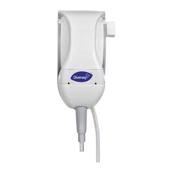
diversey QFM Kurulum ve Ayarlama Kılavuzu - Sayfa 9
Dağıtıcı diversey QFM için çevrimiçi göz atın veya pdf Kurulum ve Ayarlama Kılavuzu indirin. diversey QFM 11 sayfaları.

QFM
Setup
Select the metering peg that offers the desired dilution, using the following chart for reference. Place the letter
that is the desired setting at the bottom, where the index pin holds the metering peg in place.
Actual ratios and flow rates will vary depending on water pressure, chemical viscosity, the length of the pickup
line, the height of the unit from the floor and the level of product in the drum.
After selecting the peg setting, calibrate the dilution ratio to be sure it meets your requirements.
High flow units (Blue)
A/R Gap
A Gap
R Gap
@
@
2.5bar
1.0bar
1.5bar
A
5.8%
15.6%
16.7%
B
12.2%
14.9%
15.2%
C
11.1%
13.2%
13.3%
D
4.8%
6.3%
5.3%
E
3.8%
5.3%
4.5%
F
3.2%
3.8%
3.6%
G
2.8%
3.2%
3.0%
H
2.2%
2.8%
2.7%
I
2.0%
2.4%
2.4%
J
1.5%
1.9%
1.9%
K
1.0%
1.3%
1.3%
L
0.8%
1.0%
1.0%
M
0.6%
0.8%
0.8%
N
0.4%
0.5%
0.6%
O
0.2%
0.3%
0.3%
P
0.1%
0.1%
0.1%
Calibrate the dilution ratio as follows:
Fill a measuring/graduated cylinder with chemical.
Note the amount of chemical that is in the cylinder.
Place the foot valve fully in the chemical
Turn on the proportioner, filling a measuring container jug (high flow) or a 16-oz/500 ml measuring cup (low
flow).
Carefully withdraw the foot valve from the chemical and note the amount remaining. Subtract it from the initial
amount to calculate the amount used.
Subtract the amount of chemical used from the amount of solution collected in the measuring/graduated cylinder
to calculate the amount of water passed.
Note the amount of water : chemical to calculate dilution and the equivalent dilution as a percentage of
chemical. If necessary, repeat with different peg setting for required dilution.
Replace the cover, starting with the top sloping backwards so the plastic tabs that connect it to the backplate are
not damaged.
A/R Gap
@
@
4.5bar
15.9%
14.3%
12.0%
4.5%
3.7%
2.9%
2.4%
2.1%
1.8%
1.5%
1.0%
0.8%
0.6%
0.4%
0.2%
0.1%
Low flow units (Grey)
A Gap
A Gap
R Gap
@
@
@
1.0bar
1.5bar
1.5bar
A
23.8%
25.6%
25.0%
B
22.7%
24.4%
24.4%
C
20.4%
21.7%
21.7%
D
9.6%
10.9%
11.4%
E
8.3%
9.1%
10.0%
F
6.3%
7.1%
7.7%
G
5.3%
5.9%
6.3%
H
4.5%
5.0%
5.6%
I
3.8%
4.8%
4.8%
J
3.2%
3.8%
3.8%
K
2.3%
2.6%
2.6%
L
1.8%
2.0%
2.0%
M
1.3%
1.4%
1.5%
N
0.9%
0.9%
1.0%
O
0.4%
0.5%
0.5%
P
0.1%
0.2%
0.2%
Page 9 of 11
Installation & Setup Guide
A Gap
R Gap
A Gap
R Gap
@
@
@
2.5bar
2.5bar
4.5bar
4.5bar
23.8%
27.0%
16.1%
20.8%
23.3%
25.6%
15.4%
20.0%
21.3%
23.3%
14.1%
18.5%
10.8%
12.5%
7.7%
10.3%
9.1%
11.1%
6.7%
9.1%
7.1%
8.3%
5.3%
7.1%
5.9%
6.7%
4.2%
5.9%
5.3%
5.9%
3.7%
5.3%
4.5%
5.3%
3.2%
4.5%
3.6%
4.2%
2.6%
3.6%
2.4%
2.9%
1.9%
2.4%
2.0%
2.3%
1.4%
2.0%
1.4%
1.6%
1.0%
1.5%
1.0%
1.1%
0.7%
1.0%
0.6%
0.6%
0.4%
0.5%
0.2%
0.2%
0.1%
0.2%
DE1548 INT issB s1 July 2012
@
