Balmar 94LY Series Kurulum ve Kullanım Kılavuzu - Sayfa 15
Taşınabilir Jeneratör Balmar 94LY Series için çevrimiçi göz atın veya pdf Kurulum ve Kullanım Kılavuzu indirin. Balmar 94LY Series 20 sayfaları. Alternator
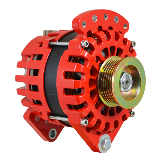
98-SERIES ALTERNATORS
Balmar's 98-Series alternators are designed to provide out-
puts of 310 amps at 12 volts, or 220 amps at 24 volts. Mount-
ing is a 4"ID J-180 saddle mount. Alternators in the 98-Se-
ries feature isolated ground terminals and a brushless rotor/
stator design that reduces alternator noise, and eliminates
key wear points.
1. Positive Output Terminal - Must be connected, via
properly-sized cable to the battery or batteries being
charged. Cable size is determined by alternator output
and length of cable run. See Page 3 for wiring size chart.
Either terminal shown may be used.
2. Negative Output Post (Ground) - Must be connected
to system ground via properly sized cable. Cable size is
determined by alternator output and length of cable run.
See Page 3 for wiring size chart.
3. Stator Output - Unrectified AC voltage can be used as
a signal for an electric tachometer. In 12-volt systems,
stator terminal will connect to WHITE wire. In 24-volt sys-
tems, the Stator Wire will connect to the ORANGE wire in
the regulator wiring harness. Any terminal can be used.
98-Series are a 14 pole stator output design.
4. External Field Terminal - Connects to external voltage
regulator via wiring harness.
5. Diode Trio (D+) Output - Provides a signal that may
be required in some systems to drive a charge indicator
lamp.
6. Temp Sensor (Not Shown) - There is a
tapped hole on the side of the rear casing
for the (Optional) MC-TS-A sensor. Do not
bend the heat shrink or ring terminal.
An unsupported cable may damage the positive or
negative terminals, resulting in damage to alterna-
tor, regulator and wiring. Ensure that cables are ad-
equately supported to supply strain relief.
NOTES:
2
3
1
OPTIONAL ACCESSORY - PART #12-98-AIR
Page 15
4
1
5