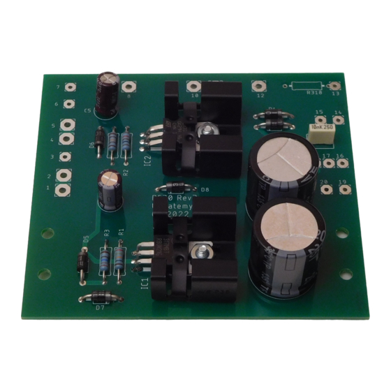
AkitikA STEREO 400 Hızlı Başlangıç Kılavuzu - Sayfa 6
Bilgisayar Donanımı AkitikA STEREO 400 için çevrimiçi göz atın veya pdf Hızlı Başlangıç Kılavuzu indirin. AkitikA STEREO 400 11 sayfaları. Pc30 replacement

Resistor Installation
These resistors are all ¼ Watt, 1%, metal film resistors. Install these resistors into the
silk-screen side of the PCB, flush with the PCB. A 1 Watt power resistor will be installed
in a later section of this manual.
Desig Value
R1
243
R2
121
R3
2260
R4
1130
R5
4020
R6
4020
Diode Installation
The diodes are rated at 1 Amp and 400 Volts. Diodes are polarized, so you must align the
white stripe on the diode with white stripe on the silk screen. Insert the diode into the silk
screen side of the board and solder them on the solder side. The diodes are installed flush
to the PCB. Note that LED's will be installed later.
Desig Type
D1
1N4004
D2
1N4004
D3
1N4004
D4
1N4004
D5
1N4004
D6
1N4004
D7
1N4004
D8
1N4004
Power Resistor Installation
Install R318, a 3.3 Ohm 1 Watt resistor.
LED Installation
Install LED1 and LED2. Unlike resistors, LEDs are polarized. There is only one right
way to install them. You can identify the positive and negative side of an LED as
follows:
1. Given uncut leads, the longer of the two leads is the ANODE (positive) lead.
2. Looking down onto the body, you'll see a round outline with a flat on one side.
That flat is closest to the CATHODE (negative) lead.
Lead spacing is 0.5"
Color Code
Red, Yellow, Orange, Black, Brown
Brown, Red, Brown, Black, Brown
Red, Red, Blue, Brown, Brown
Brown, Brown, Orange, Brown, Brown
Yellow, Black, Red, Brown, Brown
Yellow, Black, Red, Brown, Brown
Lead Spacing 0.4"
Marking
4004
4004
4004
4004
4004
4004
4004
4004
Page 6 of 11
Done
Done
