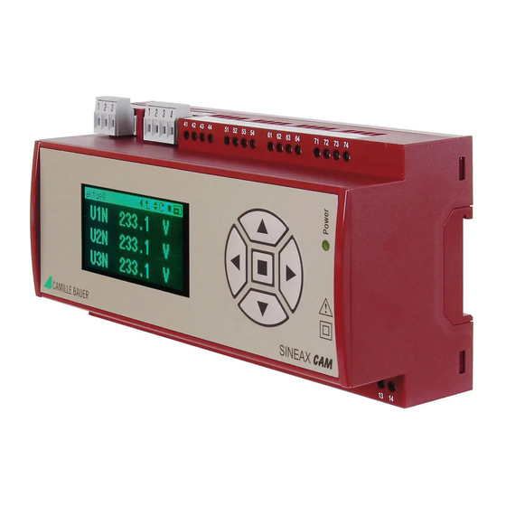
Camille Bauer SINEAX CAM Kullanım Talimatları Kılavuzu - Sayfa 6
Ölçüm Cihazları Camille Bauer SINEAX CAM için çevrimiçi göz atın veya pdf Kullanım Talimatları Kılavuzu indirin. Camille Bauer SINEAX CAM 12 sayfaları. Graphic display for sineax cam
Ayrıca Camille Bauer SINEAX CAM için: Kullanım Talimatları Kılavuzu (19 sayfalar)

5.2 Interface
RS485 bus connection (Modbus)
The terminals (1, 2, 3) are galvanically isolated from the CAM.
The signal wires (1, 2) must be twisted. The GND (3) can be
connected with a wire or the cable screen. Screened cables
must be used in an environment with interference.
The supply resistors (Rs) must be in the bus master interface.
simple RS converters do not have these resistors. Devices that
1)
Rt
+A
+A
+A
+A
-B
-B
-B
-B
1
2
1
1
1
1
1) One ground connection only. This is possibly already made at the master (PC).
Rt Termination resistors: 120 Ω each for long cables (> approx. 10 m)
Rs Bus supply resistors: 500 ... 1000 Ω each
6. Commissioning
Prior to starting, check that the connection data of the transducer agrees with the system data (see type
label).
The power supply to the transducer can then be switched on and the signals applied to the measuring inputs.
2
Type label of device with conventional current inputs
2
Type label of device with Rogowski current inputs (example with 3V supply for Rogowski coil integrator)
6
-GND
-GND
-GND
-GND
+A
+A
+A
+A
-B
-B
-B
-B
3
1
2
CAM
CAM
CAM
CAM
CAM
CAM
CAM
CAM
2
1
3A
1
3B
have resistors are e.g. W&T13601 (PC print), and W&T86201
converter from Wiesemann & Theis GmbH).
Avoid drop cables. A straight network is ideal. A maximum
of 32 devices can be connected. The bus confi guration is
made using the CB-Manager software.
MASTER
+ 3.3/+5V
Rs
Rs
RS485 Bus
+A
+A
+A
+A
-B
-B
-B
-B
-GND
-GND
-GND
-GND
3
1
2
CAM
CAM
CAM
CAM
3
Rx/Tx+,A
Rx/Tx-,B
GND
+A
+A
-B
-B
-GND
-GND
-GND
-GND
-GND
-GND
3
1
2
3
CAM
CAM
31
4
5
4
5
Rt
6
6
