Camille Bauer SIRAX BM1450 Güvenlik Talimatları - Sayfa 4
Ölçüm Cihazları Camille Bauer SIRAX BM1450 için çevrimiçi göz atın veya pdf Güvenlik Talimatları indirin. Camille Bauer SIRAX BM1450 11 sayfaları. Universal dc multifunctional indicator

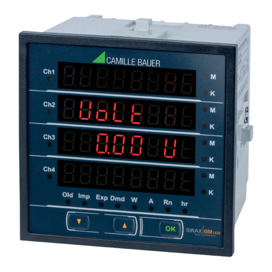
Universal multifunctional dc indicator SIRAX BM1450
Safety instructions
The unobjectionable and hazard-free operation presupposes that the
safety instructions as well as Device Manual, electronically down-
loadable via www.camillebauer.com, have been read and understood.
The installation and commissioning should only be carried out by trained
personnel.
Check the following points before commissioning:
- that the connection wires are not damaged, and that they are not live during
wiring
- that the power flow direction and the phase rotation are correct
- that these product do not have internal fuses
The instrument must be taken out of service if safe operation is no longer pos-
sible (e.g. visible damage). In this case, all the connections must be switched
off. The instrument must be returned to the factory or to an authorized service
dealer.
It is forbidden to open the housing and to make modifications to the instrument.
The instrument is not equipped with an integrated circuit breaker. During instal-
lation check that a labeled switch is installed and that it can easily be reached
by the operators.
The device is maintenance free. Unauthorized repair or alteration of the unit
invalidates the warranty.
Application area
The SIRAX BM1450 compact device is intended for firm installation and to mea-
sure dc voltage, current, frequency, power, energy (active / reactive / apparent),
power factor, phase angle, etc. in low voltage switching facilities. The meter can be
used for up to 4 channels.
Mounting
- Any mounting position is possible
- Devices with display are designed for panel mounting. The necessary panel cu-
tout and the required minimum distances are shown in figure 2. Slide the device
from outside into the cutout and fix it by means of the four mounting clamps.
Electrical connections
A marked and easily accessible current limiting switch has to be
arranged in the vicinity of the device for turning off the power supply.
Fusing should be 10 Amps or less and must be rated for the availab-
le voltage and fault current.
Attention: Danger to life! Ensure that all leads are free of potential
when connecting them!
All voltage measurement inputs must originate at circuit breakers
or fuses rated 1 Amp or less. This does not apply to the neutral
connector. You have to provide a method for manually removing
power from the device, such as a clearly labelled circuit breaker or a
fused disconnect switch.
When using voltage transformers you have to ensure that their
secondary connections never will be short-circuited.
No fuse may be connected upstream of the current measurement
inputs!
When using current transformers their secondary connectors must
be short-circuited during installation and before removing the device.
Never open the secondary circuit under load.
Cross sections and tightening torques
Terminals 1 ... 14
Single wire: ≤ 4,0mm
or multiwire with end splices: 2 x 1,5mm
2
Torque: 0.5 ... 0.6Nm rsp. 4.42 ... 5.31 lbf in
Terminal RS485 and Relay terminal
Single wire: ≤ 1,5mm
or multiwire with end splices: 2 x 0,75mm
2
Torque: max. 0.5 Nm rsp. 4.42 lbf in
4
The configuration of connections is contained in the connection diagram of Figure 3.
Technical data
Measurement inputs voltage
Nominal voltage:
Measurement inputs voltage
Nomber of channels:
Current sensor:
Shunt setting range:
Full scale setting range:
Power supply
Nominal voltage:
Nominal frequency:
Auxiliary supply burden:
RS485 output
Protocol:
Baud rate:
Cable length:
Parity:
Relay output
Relay:
Max Load voltage:
Max Load current:
Pulse rate:
Pulse duration:
Environmental conditions
Operating temperature :
Warm up time:
Relative air humidity:
Altitude :
Device to be used indoor only!
Standards and safety
Protection class:
Installation category :
Pollution degree :
Protection :
Parameterization
Complete parameterising of all functions of BM1450 is possible via 3 push-but-
tons on site or via communication interfaces Modbus (RS485). The detailed
description of the configuration and parameterization of the device is described in
2
the device manual.
2
Please observe that the data on the type plate (Fig. 1) must be
adhered to !
The national provisions have to be observed in the installation and
material selection of electric lines!
10...60 VDC (Article no. 177065)
61...200 VDC (Article no. 177073)
201...1000 VDC (Article no. 177081)
⇒ max 125% of nominal value
4
External shunt
50...150 mV
1...20 kA
⇒ max 125% of nominal value
60 ... 300V AC/DC
45 ... 50 / 60 ... 66Hz
< 6 VA
Modbus RTU
adjustable 57600, 38400, 19200, 9600, 4800
max. 1200m
Odd or Even with 1 Stopbit,
None with 1 or 2 Stopbits
N/O, COM
4
250 VAC, 30 VDC
5 A
adjustable 10, 100 or 1000
60ms, 100ms or 200ms
–10 up to +55 °C
min 3 minute
< 90% without condensation
≤ 2000 m max
II
1000 V CATII, 600 V CATIII (Measuring inputs)
300V CAT III (Power supply)
2
IP54 (front), IP20 (housing, terminals)
