Altronix SMP7PMP16 Kurulum Kılavuzu - Sayfa 3
Medya Dönüştürücü Altronix SMP7PMP16 için çevrimiçi göz atın veya pdf Kurulum Kılavuzu indirin. Altronix SMP7PMP16 4 sayfaları.
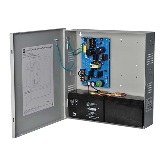
Fig. 3
1 2 3 4 5 6 7 8
Used on
PTC Models
Fig. 4
Switch disables power mains
line voltage input.
If stand-by battery (batteries) are
connected, the DC output remains on.
Fig. 4a
AC FAIL
NC C NO
NC C
LED Diagnostics
Red Green Power Supply Status
(DC) (AC)
ON
ON
Normal operating condition.
ON
OFF
Loss of AC. Stand-by battery
(batteries) supplying power.
OFF ON
No DC output.
OFF OFF
Loss of AC. Discharged or no stand-by
battery (batteries). No DC output.
Fig. 4b
Switch On - 12V
Switch Off - 24V
SW1
24VDC output - OFF
12VDC output - ON
SMP7CTX Series
Power Distribution Module(s):
common
9 10 11 12 13 14 15 16
outputs
protected
outputs
For continuous protection against risk of fire
replace fuses with same type and rating.
3.5A 250V
CAUTION: De-energize unit prior to servicing. For continued protection against fire hazard
replace fuse with the same type and rating.
ON
OFF
Wire
Green
Strap
Lead
(from
Enclosure
to Door)
115VAC
power
mains
NC
CAUTION: Optional rechargeable stand-by batteries must match
the power supply output voltage setting.
Keep power-limited wiring separate from non power-limited. Use minimum 0.25" spacing.
N
P
From
Power Supply
Board
(Factory Installed)
LOW BAT
Optional Rechargeable
Stand-by Battery
Power
Distribution
Module(s)
ON
Optional Rechargeable
Stand-by Battery
- 3 -