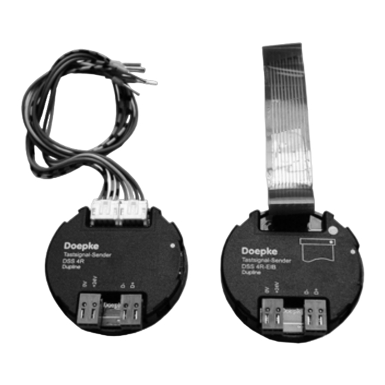
Doepke Dupline DSS 4R-EIB Kullanım Talimatları Kılavuzu - Sayfa 8
Aksesuarlar Doepke Dupline DSS 4R-EIB için çevrimiçi göz atın veya pdf Kullanım Talimatları Kılavuzu indirin. Doepke Dupline DSS 4R-EIB 12 sayfaları. Operating signal sensors with acknowledgement feature

Doepke
8. Putting into Service
8.1. General Information
Installation may only be carried out by an authorized, trained technician. Observe the
connection diagram when installing. All lines to be connected must be dead.
On both operating signal sensors the Dupline signal as well as the 24 VDC supply volt-
age should connected separately. Connections between the Dupline signal and earth
potential will cause malfunctions and are not permissible. In addition, check for the cor-
rect polarity of the Dupline signal.
Connection to the Dupline bus and the 24 VDC supply voltage is via the spring-loaded
or screw terminals provided. The following table illustrates the connection configuration:
Terminal
D+
Dupline signal conductor +
Dupline signal conductor -
D-
In order to avoid malfunctions, the lengths of the line between push-button and the sen-
sors should not exceed 1 m under normal environmental.
In order to meet the requirements for protective low voltage, VDE0100, Part 410, should
be observed and put into practice during installation. For reasons of safety and space
requirements, mains cables may not be routed through the same installation box (e.g. in
combined switch/socket units).
8.2. Connection of Push-buttons to DSS 4R
Standard push-buttons can be connected by means of the 4-wire system cable provid-
ed. In so doing care should be taken that the red 24 VDC lead of the first cable loom is
directed outwards. The following table illustrates the configuration of the connecting
leads:
Cable Loom
1
Cable Loom
2
The connection diagram is shown in Chapter 11.1 on page 11.
3931176/08/12/D - The right to make technical changes reserved!
8
Description
Pin
Color
1
2
3
yellow
4
1
green-black
2
yellow-black
7
blue-black
8
Terminal
24 VDC
Operating voltage +24 VDC
Operating voltage 0 VDC
0 VDC
red
blue
Input operating signal T1
green
Input operating signal T2
Input operating signal T4
Input operating signal T3
grey
Cathode BUS-OK-LED
Description
Signal
+24 VDC
Cathode LED1
Cathode LED2
