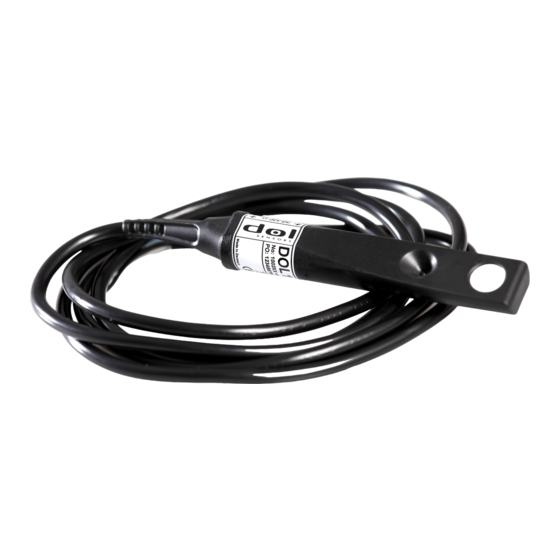
DOL 114 0-10 V Teknik Kullanım Kılavuzu - Sayfa 3
Aksesuarlar DOL 114 0-10 V için çevrimiçi göz atın veya pdf Teknik Kullanım Kılavuzu indirin. DOL 114 0-10 V 4 sayfaları. Humidity and temperature sensor

LED/LIGHT PROTOCOL
LED
Green
Red
ON
Flash
ON
Flash
4 Maintenance
Clean the sensor with water and a brush without using:
• High-pressure cleaner
• Highly compressed air
• Solvents
• Corrosive/caustic agents
• Alcohol-based disinfectants
During cleaning and disinfection, the sensor should be removed and the sealing plug for the ca-
ble should be mounted. Alternatively, the sensor protective cap can be mounted. The sensor
must be placed with the tip pointing upwards during disinfection.
After the sensor has been exposed to water and condensation, it requires a period where the relative humidity
is lower than 80 %RH in order for it to measure correctly.
Do not bend the sensor as this would inflict permanent damage on the electronics of the sensor.
5 Technical data
Specifications
Measurement range
Accuracy
Output signal
Time constant T
63
Electrical
Supply voltage
Current
Load
DOL 114 0-10 V
Status
Operation OK
Outside normal range
(below 10 % RH or exceeding 95 %
RH)
Connection error
Load < 500 Ω
Sensor defect
Over or under voltage alarm
Overload
± 2 % RH (40–85 %) ± 3 % RH
V DC
mA
Ω
Humidity measurement
0 - 100% RH
(10-95 %) at 0-40 °C
0.1 V/% RH
20 s at 0.5 m/s air speed
55 mA max. load
> 500 Ω - < 10 MΩ
www.dol-sensors.com
Functional graph
Temperature measurement
- 40 °C – 60 °C
± 0.5 °C (10 – 40 °C)
± 1.5 °C (- 30 – 60 °C)
0.1 V/°C at 4 V
6 min. at 0.5 m/s air speed
Common
11 - 30
12 mA no load
Technical User Guide
3
