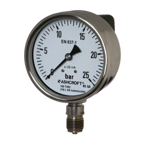
Ashcroft t5500e Kurulum ve Bakım Talimat Kılavuzu - Sayfa 7
Ölçüm Cihazları Ashcroft t5500e için çevrimiçi göz atın veya pdf Kurulum ve Bakım Talimat Kılavuzu indirin. Ashcroft t5500e 11 sayfaları. Bourdon tube pressure gauge with integrated transmitter

6 Transport
6.1 Safety
The pressure gauge should be protected against the effects of knocks and impacts. The device should only be
transported in the packaging provided to prevent damage. The device should only be transported in a clean condition
(free of residues of measuring media).
6.2 Transport inspection
Delivery should be checked for completeness and potential damage due to transport. In the event damage, delivery
must not be accepted, or only accepted subject to reservation of the scope of the damage being recorded.
6.3 Storage
The pressure gauge must be stored in dry, clean conditions, within a temperature range of -40 to +85 °C, protected
against direct exposure to sunlight and protected against impact damage.
7 Assembly/Installation
7.1 Safety
To ensure safe working during installation and servicing, suitable shut-off valves must be installed in the plant (see 5.4
Accessories) prior to enabling the device:
Relieve pressure to remove from operation;
Disconnect power for repair or inspection within the relevant plant;
Or to enable function tests of the device to be performed "on site".
During preparation to mount/install the gauge, the plant must be protected against being switched back on.
7.2 Preparations (requirements for the installation location)
A check on suitability of the device for the medium to be measured, the scope of the measurement range and of
the protection against special conditions such as vibrations, pulsations and pressure spikes.
A bracket must be installed to support the pressure gauge if the metering pipe is not able to provide adequate
support.
The installation location should be selected where no personnel operate the rear of the pressure gauge.
7.3 Mounting/Installation
7.3.1 Process connection
As standard, the device is equipped to be pipe mounted with a pressure connection shank pursuant to DIN EN 837-1.
The device is calibrated ex-works for vertical installation.
Connection to be undertaken by authorized and qualified specialist staff only.
Use only with the mechanical process connection provided – regarding the configuration, see order code on the
device type label, with a matching threaded seal.
When connecting the device, the pipes must be depressurized.
The pressure metering pipe must be laid inclined in such a way that, for example, for measurements of fluids no
air pockets can form, and for measurements of gases no water pockets. If the necessary incline is not achieved,
then at suitable points water separators or air separators must be installed.
The pressure metering pipe must be kept as short as possible and laid without sharp bends, to avoid the
occurrence of irritating delays.
With liquid measurement media, the pressurized connection pipe must be degassed, since any gas bubble
inclusions result in measurement error.
If water is used as the measurement medium, the device must be frost-protected.
Page 7 of 11
