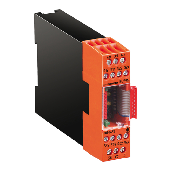
DOLD BG 5914.08/00MF0 Kullanım Talimatları Kılavuzu - Sayfa 6
I/O Sistemleri DOLD BG 5914.08/00MF0 için çevrimiçi göz atın veya pdf Kullanım Talimatları Kılavuzu indirin. DOLD BG 5914.08/00MF0 20 sayfaları. Multi-function safety system safemaster m input module

Notes
In respect of function and settings, the modules BG 5914 and BH 5914
are completely identical.
• The modules BG 5914 have 8 inputs with one common ground. This is
the ground of the overall system. They are suitable for all applications
in which volt free contacts are used, or where there is a common ground
(e.g. 2-channel light curtains). They need only 8 terminals and thus only
have an overall width of 22.5 mm.
• The modules BH 5914 have 8 completely DC-decoupled inputs. In the
settings for a 2-channel Emergency stop, several systems can be operated
from the same E-stop button.
• The modules BH 5914 must be used as soon as one Emergency stop
contact is executed on several modules. Here, short-circuit monitoring is
effected by a certain type of wiring according to the application examples.
Signal Input
This input does not have a safety function. It is used only to signal the
status of a switch (NO contact) and does not affect the safety outputs
assigned to the module (e.g. when the machine is set to service mode).
- If voltage is applied to the input, the white LED Run 2 is ON.
The semiconductor output 58 is OFF as long as no Emergency stop is active.
- If no voltage is applied to the input, the white LED Run 2 will go out,
and the semiconductor output 58 will become conductive.
Setting of the Module
In respect of function and settings, the modules BG 5914 and BH 5914
are completely identical.
The modules are assigned to the start buttons and the safety outputs via
the DIP switches.
The function is set via the rotary switches. To prevent accidently adjust-
ments, these elements are covered by a front plate and are redundant.
green LED "en 1"
0
2
3
start
output
4
input
Mod3
T1
1
1
S1
S2
9
7
8
Mod2
T2
2
2
white LED
Mod1
3
3
T3
"run 1"
Base
T4
4
4
white LED
Mod3
T1
5
5
"run 2"
Mod2
6
6
T2
Mod1
0 1 2
T3
7
7
Base
T4
8
8
5
6
9
7
M8941_b
green LED "en 2"
on
off
Note:
• Settings to the unit must be performed by skilled personnel while the
unit is off-load.
• Before the front cover is removed, potential equalization must be provi-
ded.
Sw.
Function
0
8 Emergeny stop single-channel, autostart
6 emergency stop, single-channel, + 1 emergency stop,
1
2-channel with short circuit detection, autostart
6 emergency stop, single-channel, + 1 emergency stop,
2
2-channel without short circuit detection or 1 LC type 4,
autostart
5 emergency stop, single-channel, + 1 emergency stop,
3
2-channel without short circuit detection or 1 LC type 4 + 1
signal input, autostart
4
8 Emergeny stop single-channel, manual start
6 emergency stop, single-channel, + 1 emergency stop,
5
2-channel with short circuit detection, autostart
6 emergency stop, single-channel, + 1 emergency stop,
6
2-channel without short circuit detection or 1 LC type 4,
manual start
5 emergency stop, single-channel, + 1 emergency stop,
7
2-channel without short circuit detection or 1 LC type 4 + 1
signal input, manual start
8, 9
8, 9 not assigned (error 5)
6
BG 5914.08/_0_ _ _, BH 5914.08/_0_ _ _ / 03.11.20 / 314A
plate
