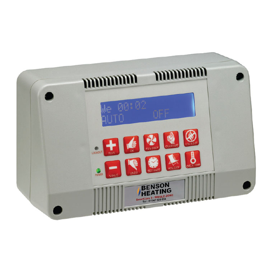
Ambirad SmartCom3 Manuel - Sayfa 9
Isıtıcı Ambirad SmartCom3 için çevrimiçi göz atın veya pdf Manuel indirin. Ambirad SmartCom3 14 sayfaları. Control panel & nor-ray-vac radiant system
Ayrıca Ambirad SmartCom3 için: Teknik Bülten (4 sayfalar), Kurulum Kablolaması (8 sayfalar)

8 Modulation Damper and Pressure Switches
The fan damper is wired via a plug and socket arrangement. The socket is connected to the
assembly via a bracket.
Release the loose plug and
remove the cap via two screws.
Connect
the
incoming
cable from the Control panel
onto terminals L3 and GND,
ensuring correct orientation.
Connect the incoming 4-20mA
cable
from
the
modulation
thermostat onto
terminals L1
and GND, ensuring correct
orientation.
Refer to low voltage external
wiring diagram for control panel
and
modulation
thermostat
terminations.
Replace the cap and plug into
socket.
SCHEMATIC DIAGRAM
PRESSURE SWITCH CONNECTIONS
The pressure switch is attached to the damper
assembly
Release the plastic cap via two screws.
Connect the incoming cable to terminals:
1 - normally closed contact
3 - common contact
Refer to low voltage external wiring diagram for
control panel terminations.
Replace the plastic cap via two screws.
24V
FIXED CONNECTION
SOCKET
L1
G
L3
24V AC LINE
VOLTAGE
FROM PANEL
1
CONTRACTORS
CONNECTION PLUG
4 - 20mA
FROM
THERMOSTAT
PRESSURE
SWITCH
3
