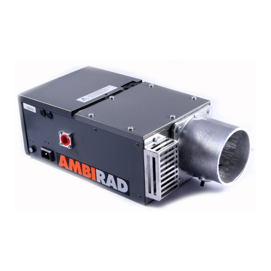
Ambirad ARE22 SL Посібник з монтажу та обслуговування - Сторінка 17
Переглянути онлайн або завантажити pdf Посібник з монтажу та обслуговування для Газовий обігрівач Ambirad ARE22 SL. Ambirad ARE22 SL 20 сторінок. Gas fired radiant tube heaters

- 1. Table of Contents
- 2. AR and ARE Series Gas Fired
- 3. Gas Connection
- 4. Standards
- 5. Assembly Instructions
- 6. Fitting Reflectors and End Caps
- 7. Burner/Fan/Damper Assembly
- 8. AR and ARE Series Double Linear
- 9. HB and DL Damper Settings
- 9. Installation – Suggested Methods
- 9. Of Heater Suspension
- 10. Flue Connection
- 11. Commissioning for Individually
- 12. Routine Service
- 13. Trouble Shooting Checklist
- 14. User Instructions for Ambi-Rad
16 Routine service
ID fan
Remove ID fan by unplugging the electrical
connection from the burner/control
assembly and loosening the fan securing
pinch screw. If a flue is fitted, this must be
disconnected. The fan will now slip off the
emitter tube. Inspect the main fan impeller
and remove any dust by brushing with a
soft brush. Similarly remove any dust from
the finger guard covering the secondary
(cooling) impeller and the mesh aperture
in the motor cover. Ensure that the impeller
turns freely and that there is not excessive
play in the bearings. Do not replace fan until
emitter tube inspection has been completed.
Emitter tube inspection
Brush away any dust on the exterior of the
emitter tubes.
Inspect the emitter tubes internally. If there
is any appreciable build up of dust or
deposits the tubes should be cleaned
internally. Remove the burner/control
assembly as directed below.
Detach return bend and remove the
turbulators where fitted. The two tubes can
then be cleaned by passing rods and a
suitable scraper through them or by use of
an industrial vacuum cleaner with a long
extension tube.
Reflector
Although not considered part of an annual
routine service, the condition of the reflector
should be noted and the user's attention
drawn to any cleaning necessary. The
reflectors can be simply withdrawn for
cleaning by removing the M6 nuts and bolts
securing them and sliding them out of the
suspension brackets once the reflector end
caps have been removed. The reflectors can
be cleaned with a soft cloth and detergent
in water. A mild non abrasive metal polish
may be used in cases of extreme
discolouration. Dirty reflectors will increase
the heat radiation upwards into the roof
space by 3-4%.
Removal of burner/control assembly
Remove the burner/control assembly by
disconnecting the gas and electrical
supply, fresh air inlet (if fitted) and the
fan electrical connection. Slacken the
burner fixing pinch screws and draw the
assembly off the emitter tube.
Burner/electrode assembly
Inspect the burner electrode assembly by
removing six dome head screws securing
the combustion chamber's cover plate on
top of the burner box, taking care not to
damage the sealing gasket. Remove the
burner head by unscrewing it from the
injector, taking care not to drop it onto
the leads of the ignition electrodes.
Pepper pot burner heads should be
examined every 6 months for signs of
debris and cleaned by blowing compressed
air in reverse direction to flow. Renew the
electrode assembly if it is not in good con-
dition. The assembly is then lifted out of
the combustion chamber and the two
connection cables disconnected.
If the electrode assembly is in good order
check the spark electrode gap. This should
be 3.5mm ± 0.5mm. Adjust the gap if
necessary by bending the earth rod. Refit
the electrode assembly in the reverse order
of removal, ensuring that the electrical
connections to the assembly are the
correct way round and secure.
Inspect the injector and clean as necessary.
Do not broach out. To remove the injector
with the burner head removed, unscrew
the injector from its carrier using a spanner
on the hexagon portion of its body. When
replacing the injector ensure that it is fully
tightened in its carrier. Replace the burner
head. Replace the combustion chamber
plate cover, renewing the sealing gasket if
this is not in good condition.
17 Replacement of components
Health and safety
Isolate gas and electrical supplies before
carrying out any repair work. Always test
for gas soundness with a suitable leak
detection fluid.
To replace ID fan
Remove ID fan connecting plug from the
burner control assembly. Disconnect flue if
fitted. Slacken pinch screw securing fan to
emitter tube. Draw fan off tube. Remove three
M5 screws securing fan support to fan
casting. Refit support flange to new fan with
the pinch bolt facing in the same direction as
the flue outlet. Refit the fan to the heater,
ensuring that the fan discharge faces upwards
for flued heaters or horizontally away from
the burner for unflued heaters.
To replace any components in
the burner/control assembly
This assembly should be removed from the
heater by first disconnecting the gas and
electrical supplies and the fan electrical con-
nection. Slacken the securing pinch screws
and draw the burner/control assembly off the
emitter tube. When refitting the burner
assembly to the heater ensure the box is
horizontal ie. with indicator lamps
downwards.
To replace electrode assembly
Remove top cover of combustion chamber
by removing the six dome headed fixing
screws, taking care not to damage the gasket.
Remove the M4 screws securing the electrode
assembly and pull off the two electrode
cable connectors. Reconnect the cable
connectors to the new electrode assembly
(the two connectors are non interchangeable)
and refit the electrode assembly. Refit the
combustion chamber cover plate and sealing
gasket. Replace the sealing gasket if this
is damaged.
To replace burner head
Remove combustion chamber as above.
Unscrew burner head from the injector,
taking care not to drop it onto the ignition
leads. Refit new burner head and replace
combustion chamber cover plate, replacing
the gasket if this is damaged.
17
