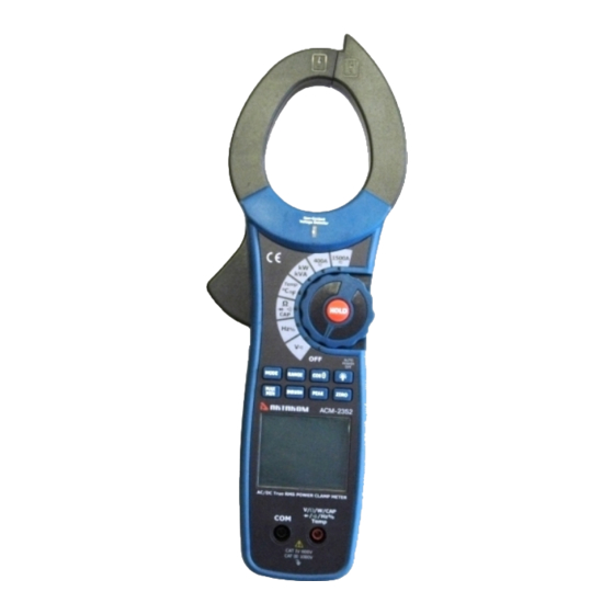
Aktakom ACM-2352 Посібник користувача - Сторінка 4
Переглянути онлайн або завантажити pdf Посібник користувача для Вимірювальні прилади Aktakom ACM-2352. Aktakom ACM-2352 8 сторінок. Clamp & watt meter

Operation
NOTES: Read and understand all Warning and Caution statements in this operation manual prior to using this meter. Set the function
select switch to the OFF position when the meter is not in use.
Non-Contact Voltage Detector
WARNING: Risk of Electrocution. Before use, always test the Voltage Detector on a known live circuit to verify proper operation.
1.
Rotate the Function switch to any measurement position.
2.
Place the detector probe tip on the conductor to be tested.
3.
If AC voltage is present, the NCV detector will turn on with a steady red light.
NOTE: The conductors in electrical cord sets are often twisted. For best results, move the probe tip along a length of
the cord to assure placing the tip close to the live conductor.
NOTE: The detector is designed with high sensitivity. Static electricity or other sources of energy may randomly trip
the sensor. This is normal operation.
AC/DC Current Measurements
WARNING: Disconnect the test leads before measuring with clamp.
1.
Rotate the Function switch to the 1500A
2.
Press the MODE button to select AC or DC.
3.
Press the trigger to open jaw. Fully enclose only one conductor.
4.
Read the current value in the display.
5.
If the value is less than 400A, rotate the function switch to the 400A
resolution.
DCA Zero
The Zero feature removes offset values and improves accuracy for DC current
measurements. To perform a zero, select A
button. The display will show zero. The offset value is now stored and removed from all
measurements.
Frequency
When ACV is selected, the measured frequency can be viewed in the lower display.
AC/DC Voltage Measurements
CAUTION: Do not measure voltages if a motor on the circuit is being switched ON or OFF. Large voltage surges may occur that can
damage the meter.
1.
Rotate the function switch to the V position.
2.
Press the MODE button to select AC or DC Voltage.
3.
Insert the black test lead banana plug into the negative COM jack.
Insert the red test lead banana plug into the positive V jack.
4.
Touch the black test probe tip to the negative side of the circuit.
Touch the red test probe tip to the positive side of the circuit.
5.
Read the voltage value in the display.
Frequency
When ACA is selected, the measured frequency can be viewed in the
lower display.
Resistance Measurements
Note: Remove power from the device under test before measuring resistance.
Set the function switch to the Ω position.
1.
2.
Insert the black test lead banana plug into the negative COM jack.
Insert the red test lead banana plug into the positive V jack.
3.
Touch the black test probe tip to one side of the device to be measured.
Touch the red test probe tip to the other side of the device to be measured.
4.
Read the resistance value in the display.
Continuity Test
1.
Connect as described for resistance measurements.
2.
Press the MODE button to select continuity
3.
Touch the test probe tips across the circuit or component under test.
position.
AC/DC
AC/DC
and, with no conductor in the jaw, press the ZERO
DC,
•
).
)
)
www.tmatlantic.com
position to improve
4
