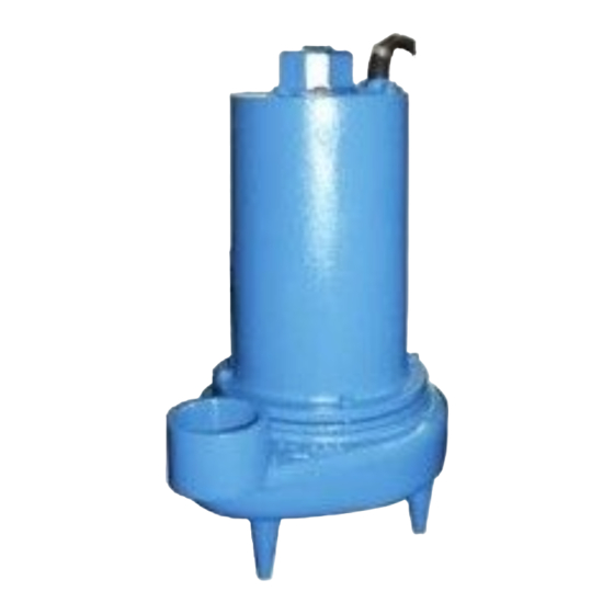
Barnes 3SE-DS Series Посібник з монтажу та експлуатації - Сторінка 6
Переглянути онлайн або завантажити pdf Посібник з монтажу та експлуатації для Водяний насос Barnes 3SE-DS Series. Barnes 3SE-DS Series 20 сторінок. Submersible sewage ejector
Також для Barnes 3SE-DS Series: Посібник з монтажу та експлуатації (17 сторінок), Посібник з монтажу та експлуатації (18 сторінок)

C-4) Electrical Connections:
C-4.1) Power & Control Cords:
The cord assembly mounted to the pump must not be modifi ed
in any way except for shortening to a specifi c application.
Any splice between the pump and the control panel must be
made in accordance with all applicable electric codes. It is
recommended that a junction box, if used, be mounted outside
the sump or be of at least NEMA 4 (EEMAC-4) construction if
located within the wet well. DO NOT USE THE POWER OR
SENSOR CORDS TO LIFT PUMP.
NOTE: The white wire is not a neutral or ground
lead. The black, white and red leads are power
carrying conductors. The green lead is for
connection to ground.
C-4.2) Overload Protection :
C-4.2-1) Single and Three Phase - The normally closed
(N/C) thermal sensor is embedded in the motor windings and
will detect excessive heat in the event an overload condition
occurs. The thermal sensor will trip when the windings become
too hot and will automatically reset itself when the pump
motor cools to a safe temperature. It is recommended that the
thermal sensor be connected in series to an alarm device to
alert the operator of an overload condition, and/or the motor
starter coil to stop the pump. In the event of an overload, the
source of this condition should be determined and rectifi ed
immediately. DO NOT LET THE PUMP CYCLE OR RUN IF
AN OVERLOAD CONDITION OCCURS !
immediately. DO NOT LET THE PUMP CYCLE OR RUN IF
AN OVERLOAD CONDITION OCCURS !
MODEL
HP VOLT/PH Hz
NO
3SE3024DS
3.0
230/1
3SE3034DS
3.0
230/3
3SE3044DS
3.0
460/3
3SE3054DS
3.0
575/3
Winding Resistance ± 5%.
Moisture & Temperature sensor cord for all models is 18/5 SOOW/SOW, 0.47" (11.9mm) O.D.
RPM
NEMA
INSUL.
(Nom)
START
CLASS
CODE
60
1750
A
60
1750
D
60
1750
D
60
1750
E
Pump rated for operation at ± 10% voltage at motor.
C-4.3) Moisture Sensors:
A normally open (N/O) detector is installed in the pump
seal chamber which will detect any moisture present. It is
recommended that this detector be connected in series to an
alarm device or the motor starter coil to alert the operator that
a moisture detect has occurred. In the event of a moisture
detect, check the individual moisture sensor probe leads
for continuity, (∞ resistance = no moisture ) and the junction
box/control box for moisture content. The above situations
may induce a false signal in the moisture detecting circuit. If
none of the above test prove conclusive, the pump(s) should
be pulled and the source of the failure identifi ed and repaired.
IF A MOISTURE DETECT HAS OCCURRED SCHEDULE
MAINTENANCE AS SOON AS POSSIBLE.
If current through the temperature sensor exceeds the values
listed, an intermediate control circuit relay must be used to
reduce the current or the sensor will not work properly.
TEMPERATURE SENSOR ELECTRICAL RATINGS
Volts
220-240
440-480
575-600
C-4.4) Wire Size:
Consult a qualifi ed electrician for proper wire size if additional
power cable length is required. See table for electrical
information.
FULL
LOCKED
CORD
LOAD
ROTOR
SIZE
AMPS
AMPS
F
28.0
59.0
10/3
F
19.0
56.0
12/4
F
9.0
28.0
14/4
B
5.9
23.0
14/4
6
Continuous
Inrush
Amperes
Amperes
1.50
0.75
0.60
CORD
CORD
TYPE
O.D
inch (mm)
MAIN - START
SOOW/SOW
.66 (16.8)
SOOW/SOW
.68 (17.4)
SOOW/SOW
.57 (14.5)
SOOW/SOW
.57 (14.5)
15.0
7.5
6.0
WINDING
RESISTANCE
0.84 - 4.0
1.40
6.30
9.90
