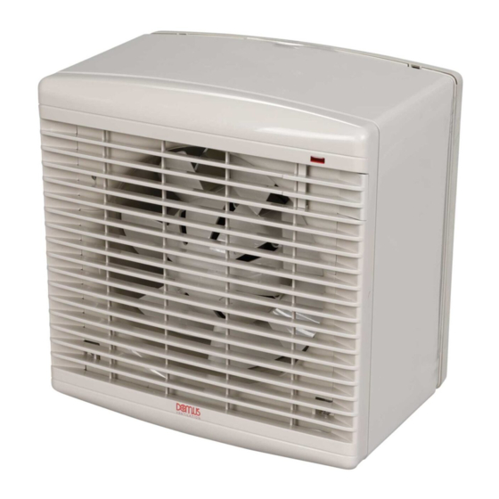
Domus Ventilation DX6WW Посібник з монтажу та обслуговування - Сторінка 4
Переглянути онлайн або завантажити pdf Посібник з монтажу та обслуговування для Вентилятор Domus Ventilation DX6WW. Domus Ventilation DX6WW 8 сторінок. Window fan kit 50hz/60hz, supply / extract units

Installation and Maintenance
DX Window Fan Kit 50Hz/60Hz
5.0 Electrical Installation
5.0 Electrical Installation
5.0 Electrical Installation
Electrical work should be undertaken by a qualified electrician in accordance with the wiring regulations.
Electrical work should be undertaken by a qualified electrician in accordance with the wiring regulations.
Electrical work should be undertaken by a qualified electrician in accordance with the wiring regulations.
1
1
1
Release the electrical panel from the fan plate.
Release the electrical panel from the fan plate.
Release the electrical panel from the fan plate.
3
3
3
Clamp the cable and complete the connections.
Clamp the cable and complete the connections.
Clamp the cable and complete the connections.
5.1 Wiring
5.1 Wiring
5.1 Wiring
5.1.1 Fan Operated By On / Off Switch
5.1.1 Fan Operated By On / Off Switch
5.1.1 Fan Operated By On / Off Switch
Double pole
Double pole
Double pole
Fuse
Fuse
isolator
isolator
isolator
max. 3 amp
max. 3 amp
L
L
L
N
N
N
Connect link wire between L2 & L4 for extract OR
Connect link wire between L2 & L4 for extract OR
Connect link wire between L2 & L4 for extract OR
connect link wire between L2 & L3 for supply.
connect link wire between L2 & L3 for supply.
connect link wire between L2 & L3 for supply.
5.1.2 Fan Operated By Integral Sensor
5.1.2 Fan Operated By Integral Sensor
5.1.2 Fan Operated By Integral Sensor
SL
SL
SL
(Switched Live)
(Switched Live)
(Switched Live)
Double pole
Double pole
Double pole
Fuse
Fuse
isolator
isolator
isolator
max. 3 amp
max. 3 amp
L
L
L
N
N
N
Connect link wire between L2 & L4 for extract OR
Connect link wire between L2 & L4 for extract OR
Connect link wire between L2 & L4 for extract OR
connect link wire between L2 & L3 for supply.
connect link wire between L2 & L3 for supply.
connect link wire between L2 & L3 for supply.
Connect switched live signal to L5 for integral timer module.
Connect switched live signal to L5 for integral timer module.
Connect switched live signal to L5 for integral timer module.
LAB1350R May 2018
L5
L5
L4
L4
or
or
or
L3
L3
Fuse
L2
L2
max. 3 amp
L1
L1
N
N
DX Fan unit
DX Fan unit
L5
L5
L4
L4
or
or
or
L3
L3
Fuse
L2
L2
max. 3 amp
L1
L1
N
N
DX Fan unit with
DX Fan unit with
DX Fan unit with
integral sensor
integral sensor
integral sensor
2
2
2
Remove the terminal cover.
Remove the terminal cover.
Remove the terminal cover.
4
4
4
Refit terminal cover before replacing the electrical panel.
Refit terminal cover before replacing the electrical panel.
Refit terminal cover before replacing the electrical panel.
5.1.3 Basic Fan Operated By Remote Sensor
5.1.3 Basic Fan Operated By Remote Sensor
5.1.3 Basic Fan Operated By Remote Sensor
L5
L4
Double
Double
Double
L3
Fuse
Fuse
pole
pole
pole
max.
max.
L2
isolator
isolator
isolator
3 amp
3 amp
L
L
L
L1
N
N
N
N
DX Fan unit
Connect link wire between L2 & L4 for extract OR
Connect link wire between L2 & L4 for extract OR
Connect link wire between L2 & L4 for extract OR
connect link wire between L2 & L3 for supply.
connect link wire between L2 & L3 for supply.
connect link wire between L2 & L3 for supply.
L5
IMPORTANT
IMPORTANT
IMPORTANT
L4
L3
Isolation - Before commencing work, make sure that the unit is
Isolation - Before commencing work, make sure that the unit is
Isolation - Before commencing work, make sure that the unit is
electrically isolated from the mains supply.
electrically isolated from the mains supply.
electrically isolated from the mains supply.
L2
L1
N
V E N T I L A T I O N
Remote sensor
Remote sensor
Remote sensor
L1
L1
L2
L2
L1
N
N
L2
N
or
or
or
Fuse
max.
3 amp
DX Fan unit
DX Fan unit
L5
L5
L5
L4
L4
L4
L3
L3
L3
L2
L2
L2
L1
L1
L1
N
N
N
DX Fan unit
Page 4
