Ekinex EK-BH1-TP-485 Посібник - Сторінка 2
Переглянути онлайн або завантажити pdf Посібник для Шлюз Ekinex EK-BH1-TP-485. Ekinex EK-BH1-TP-485 4 сторінки. Gateway modbus master rtu rs485 - knx tp

7
6
12
11
ETHERNET
10
Failure
KNX
Modbus
9
Device state
EK-BH1-TP-485
8
Modbus Master RS485 RTU
/ KNX TP Converter
2
1
5
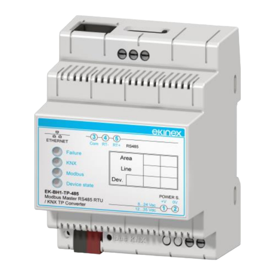
KNX bus line terminal blocks
1)
KNX programming pushbutton
2)
KNX programming LED
3)
Power supply terminal blocks
4)
1-way microswitch A
5)
Ethernet port
6)
Ethernet port LED
7)
Device satus LED
8)
Modbus communication LED
9)
KNX communication LED
10)
Device error LED
11)
RS485 serial line terminal blocks (3 Com, 4 RT-, 5 RT+)
12)
1-way microswitch B
13)
Command elements
•
Pushbutton that switches between normal mode and
KNX physical address programming.
1-way microswitches
•
A - OFF: normal mode active. ON: Boot mode active
•
B - OFF: open. ON: RS485 line termination inserted
(120 termination resistance in parallel between
RT+ and RT-)
Display elements
The device can run according to two operating modes:
Normal mode (configuration loaded, Modbus and KNX
communication
running)
configuration or configuration still loading).
•
Green LED (8) – Device status. Normal mode: Slow
blinking (~1 Hz). Boot mode: ON= device on; OFF=
device off.
•
Yellow LED (9) – Modbus communication. Normal
mode: blinks when a frame is received on the RS485
port. Boot mode: if fast blinking: no configuration, if
very slow blinking (~0,5 Hz): loading configuration.
13
3
4
5
Com
RT-
RT+
RS485
Area
Line
Dev.
POWER S.
+V
0V
8...24 Vac
1
2
12...35 Vdc
3
4
ON
and
Boot
mode
•
Yellow LED (10) – KNX communication. Normal
mode: blinks when a frame is received. Boot mode: if
fast blinking: no configuration, if very slow blinking
(~0,5 Hz): loading configuration.
•
Yellow LED (11) – Device error. Normal mode: ON=
at least one Modbus request did not get a correct
answer; OFF= no error. Boot mode: if fast blinking:
no configuration, if very slow blinking (~0,5 Hz):
loading configuration.
•
Green LED (7) – Ethernet port. Normal mode: ON=
Ethernet
connector unplugged. Boot mode: ON= Ethernet
connector
unplugged.
•
Red LED (3) – KNX programming. Normal mode:
ON= physical address programming mode on; OFF=
physical address programming mode off. Boot mode:
if fast blinking: no configuration, if very slow blinking
(~0,5 Hz): loading configuration.
Installation
The device has IP20 protection degree and is therefore
suitable for dry indoor environments. The case is suitable
for mouting on a DIN rail (according to EN 60715) inside
eletrical distribution cabinets. The proper installation
involves the bus terminal blocks to be in the lower side.
For installation proceed as follows:
•
with the aid of a tool bring the locking device in
completely lowered position (1);
•
place the device on the upper edge of the DIN rail
(2);
•
rotate the device towards the DIN rail (3);
•
push the locking device up untili il stops (4).
To unmount the device, make sure to unplug the network
connection and the bus terminal from its housing. Use a
(no
screwdriver to slide down the lock and remove the device
from the rail.
Note. It is recommended to install the device so to
always guarantee full frontal accessibility, in order to
properly display the status LEDs.
Power supply connection
The device supports a very wide range of supply
Pag. 2
connector
plugged;
OFF=
plugged;
OFF=
Ethernet
1
3
Ethernet
connector
2
4
