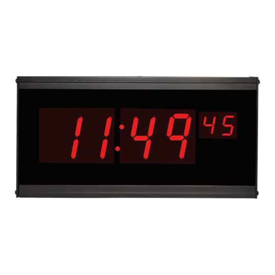
American Time DSY261RSxE Посібник з монтажу та експлуатації - Сторінка 8
Переглянути онлайн або завантажити pdf Посібник з монтажу та експлуатації для Годинник American Time DSY261RSxE. American Time DSY261RSxE 17 сторінок. Digital clock/elapsed time indicator with code blue

Clock/Timer Installation
The Digital Clock/Timer can be mounted to a single or double gang box. To install the Digital Clock/Timer, follow the
instructions below. Ensure that installation conforms to the National Electrical Code and local wiring codes.
CAUTION: Electric Shock Hazard! Ensure that NO electrical power is present on any wire before installation.
u
Remove the 6-32 black screw on the top of the clock which secures the back mounting plate. Mount the back plate to
a single or double gang box. See Figure 2 below.
v
Make electrical connections (hot, neutral, ground and optional correction wires) to non-switched electrical circuit
wiring using UL approved wire nuts. Route field wiring away from sharp projections, corners and internal components.
For Molex, connect white to neutral/common, black to positive/hot, green to ground and red to optional correction line
if using a wired master. Note: Voltage and frequency is set at the factory. See part number suffix reference.
120vac 60 Hz (DSY261RSAE and DSA261RSPE)
220vac 60Hz (DSY261RSKE)
w
Pull the ten wires from the clock to the control station. Keep these ten wires separate from the high voltage wires.
See Figure 1 below. Note: there are two wires (white and green) in the bundle that are not used.
x
Join the two Molex connectors together, placing excess wiring and Molex connectors into the gang box.
y
Slide the clock onto the metal mounting bracket installed in Step 1 and reinsert 6-32 screw from the top of the clock
into the mounting bracket hole. See Figure 2 below.
z
Connect field wiring interconnecting the Clock/Timer with the ATSTCS Control Station to the appropriate
terminals of the Digital Clock/Timer See wiring detail on next page.
Chassis ground MUST be connected to conduit/Earth ground to provide proper protection from electric shock.
CAUTION: Electric Shock Hazard! When making installation, route field wiring away from sharp projections, corners, and
internal components.
Apply power to the circuit and confirm correct operation.
Figure 1
8
DSY261RSxE Owner's Manual
24vac 60 Hz (DSY261RSBE)
220vac 50Hz (DSY261RSKE50H)
Mounting plate detail
Mounting plate
fastens to the
back box
6-32 x
/
black screw
3
4
secures device to the
mounting plate
Single or double gang
box (supplied by others)
must be securely mounted
Figure 2
© American Time
