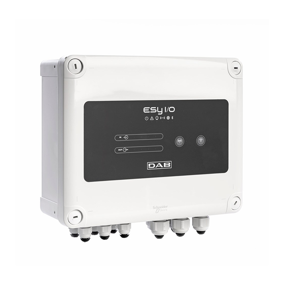
DAB ESY I/O Інструкція з монтажу та обслуговування - Сторінка 6
Переглянути онлайн або завантажити pdf Інструкція з монтажу та обслуговування для Блок управління DAB ESY I/O. DAB ESY I/O 16 сторінок.

4.
Screw the panel onto the wall
Before screwing the panel back on, make sure that the cable between the two boards is correctly connected!
2.1 Electrical connections
ESY I/O requires the connection of an L-N single-phase power supply cable, the characteristics of which must be as follows:
Single cable copper section minimum 0.8mm
-
-
Maximum sheath diameter 10mm
Minimum sheath diameter 5mm
-
1. Insert the cable in the cable gland shown in Figure 1, circled in orange (Cable gland 3)
2. Connect the power cable before closing the front panel as shown below:
3. Tighten the cable gland to maintain the IP rating of the panel
Depending on the application, the user can make other electrical connections, see Figure 1.
The cable glands in section 1 are used to wire Inputs (see Paragraph 2.7), pressure sensor (see Paragraph 2.9) and Rs485 Modbus (see
Paragraph 2.10).
The cable glands in section 2 are used to wire Outputs (see Paragraph 2.8).
ENGLISH
5.
Replace the clips for tightening
the plastic screws of the panel
(AWG 18)
2
Figure 1: Front view of cable glands
15
6.
Screw the panel on again
