DoorHan GC4 Посібник з монтажу та експлуатації - Сторінка 3
Переглянути онлайн або завантажити pdf Посібник з монтажу та експлуатації для Блок управління DoorHan GC4. DoorHan GC4 4 сторінки. Group control unit

1. INTENDED USE OF THE PRODUCT
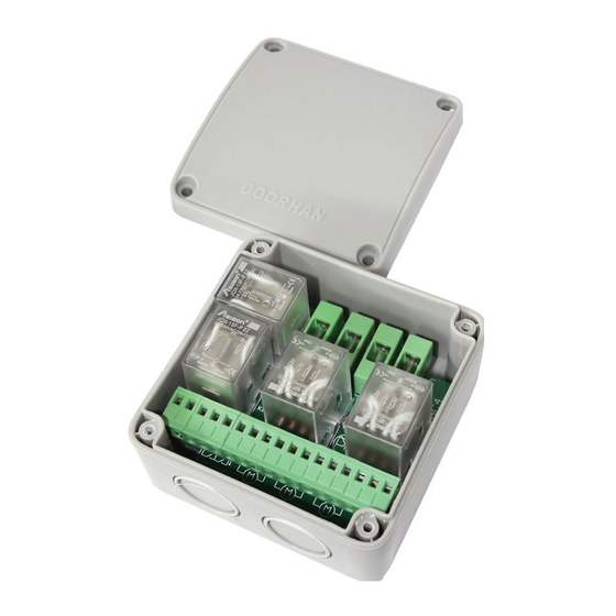
GC4 group control unit is intended to control simultaneously several electric operators
(up to 4) from the central switch. You can combine several control units to control 8, 12
or more electric operators from one or more central switches. The device has a function
of protection from overpower and simultaneous activation of two move directions (buttons
"Up" and "Down").
2. SPECIFICATIONS
Supply voltage
Maximal allowable switching current
Switching voltage
Number of operators controlled
Dimensions
Environment temperature
Housing protection rating as per GOST 14254
Electric protection class as per GOST 27570
3. INSTALLATION
1. Remove protective packaging of the control unit. Remove
the cover of the control unit housing using a screwdriver.
2. Unscrew two fixing bolts of the control unit panel and take
it out of the housing.
3. Connect wiring according to the diagram (Fig. 2).
4. Fix the control unit panel in the housing and place the cover
back.
When installing, protect the device from dust and moisture.
When connecting equipment wires, if possible, use the mount-
ing holes positioned on the side of the terminal block (not on
the top). Before connecting, pierce the rubber plugs using an
awl or a thin screwdriver (Fig. 1) so that the diaphragm fits
tightly the inserted wires.
4. WIRING
Contact function (Fig. 2)
1. Supply mains neutral ~220 V
2. Supply mains phase ~220 V
3. Direction "A" of operator
4. Common wire of switch
5. Direction "B" of switch
6, 9, 12, 15. Direction "A" of operator (black wire)
7, 10, 13, 16. Neutral of operator (blue wire)
8, 11, 14, 17. Direction "B" of operator (brown wire)
220 V, 50 Hz
Installation Recommendations
1. To connect supply mains 220 V 50 Hz, use the wire with double insulation and 1.5–
2.5 mm
cross-section core.
2
2. To connect switches, you can use a wire with 0.75 mm
an electric operator, use a wire with 0.75–1.5 mm
installation, you should use cable pipes with protection rating IP65.
NOTE: If the total power of all electric operators used exceeds 1,5 kW, you should divide
them into groups, power of each is from 1 to 1,5 kW, and connect supply voltage to each
group by an individual cable from the electrical control unit. These groups can be also
distributed between various phases of 3-phase electricity supply network.
R2
R1
1
2
3
4
5
N 220В -
N
L
Switch
Fig. 2. GC4 group control connection diagram
GC4 GROUP CONTROL UNIT
INSTALLATION AND OPERATION GUIDE
R4
6
7
8
9
10
11
12
M
M
220 V, 50 Hz
≤ 3 А
220±10 V
98 × 98 × 56 mm
from –40 to +45°С
IP65
II (no protective grounding
is required)
Fig. 1. Hole making
R3
13
14
15
16
17
M
cross section core. To connect
2
cross-section core. For outdoor
2
2
