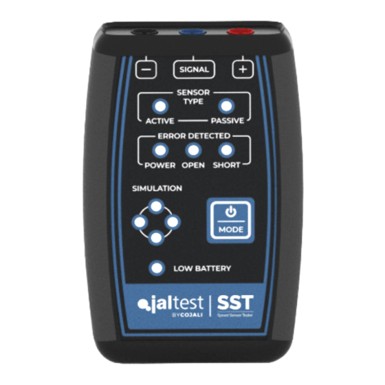
Cojali Jaltest SST Посібник користувача - Сторінка 8
Переглянути онлайн або завантажити pdf Посібник користувача для Випробувальне обладнання Cojali Jaltest SST. Cojali Jaltest SST 15 сторінок. Speed sensor tester

· PASSIVE speed sensor:
In this mode, the speed sensor is disconnected from the ECU and connected to the
Jaltest SST device to be able to check it in isolation. By turning the component whose
sensor the user wants to check, they can determine if the sensor generates a correct
signal. For example, by manually turning a vehicle wheel with speed sensor.
1
Disconnect the speed sensor from the vehicle and connect it to the Jaltest SST
device through multipins according to the
section.
2
Turn on the device and go into
selection button of the mode (1) according to the presses described in the
table
on page 6. The
that may appear.
3
Turn the component whose sensor you want to check.
4
Signal check: When the wheel is turning at fixed speed, the status LEDs of the
signal must flash sequentially and constantly.
5
Error check:
ٚ The status LED of the signal flash inconsistently: the sensor does not detect a
consistent turn signal.
ٚ The
open circuit error
ٚ The
short circuit error
supply has occurred during the execution of the test.
ٚ The
power supply error
(simulation).
Note: It is possible to repeat the test with just a short press of the selection button of the Mode. The
device performs an error reset and starts the test again.
2.2 SIMULATION MODE
Important!
Jaltest SST cannot operate as a substitute for the vehicle speed sensor
so, in some cases, it is normal that the ECU has present errors concerning the
disconnected component.
ACTIVE speed sensor:
In this mode, the Jaltest SST device generates a signal that simulates the behaviour
of an active sensor. When connecting the Jaltest SST device to the ECU and with
Passive Sensor Read
Passive Sensor
LED must be on, as well as the LED of the errors
LED lights up: Wiring or sensor is defective.
LED lights up: Short circuit to ground (chassis) or power
LED lights up: Incorrect mode has been selected
IMAGE 2
of the connection
mode interacting with the
8
English
diagram
function
