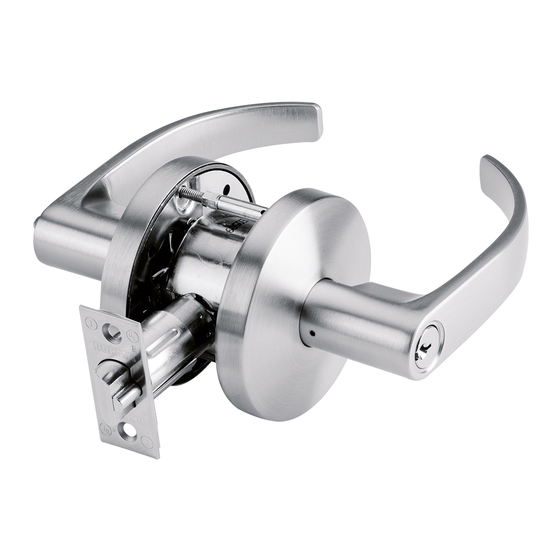
Dorma C500 Інструкція з монтажу
Переглянути онлайн або завантажити pdf Інструкція з монтажу для Замки. Dorma C500. Dorma C500 2 сторінки. Cylindrical leverset

C500 CYLINDRICAL LEVERSET
—
Installation Instructions
Overall Exploded View
Part List
15 - 10-32 x 1-½ "
8 - Latch sleeve
1 - IC core
9 - Latch fi ller plate
2 - Outside IC lever
16 - Inside rose
10 - Latch
3 - Outside
11 - 8-32 x ¾ " combo
17 - Lever insert
conventional
screws (x2)
18 - Inside lever
cylinder lever
12 - Mounting plate
19 - M5-0.5 x
4 - Conventional
13 - 10-32 x 1-½ " screws (x2)
cylinder
14 - Spring cage
5 - Thru-bolt studs
6 - Outside rose
assembly
7
7 - Lock assembly
3
5
4
6
2
1
2. Install lock assembly
Adjust for door thickness
2.2 Remove the outside lever
NOTE: Lock comes adjusted
-¾ "
and separate the outside rose
for 1
door from the factory.
assembly from the
2.1 To adjust the lock
adjustment plate.
assembly for door
thickness, align the
2.3 Rotate the adjustment plate
center of the chassis
to adjust for proper
with the center of the
door thickness.
latch.
2.4 Realign & install the outside
rose assembly. Replace the
outside lever.
(See supplementary
Outside rose
Center of
sections II & III.)
assembly
latch
Chassis
Adjustment
plate
Outside rose
assembly
Outside
2
lever
www.dorma.com
m
screws (x2)
⅜
"
screws
17
16
15
14
13
12
11
8
9
10
Thru-bolt installation (preferred)
2.5 Slide the lock assembly into the face of
the door.
Be sure to engage the inner latch
mechanism of the chassis with the
mechanism of the chassis with the
back of the latch
as shown.
as shown.
Latch
Lat
Chassis
Tools required for installation
Tools required for installation
#2 Cross drive screwdriver
#2 Cross drive screwdriver
Flathead screwdriver
Flathead screwdriver
18
7
3
6
4
2
8
1
Non-thru-bolt installation
3. Install mounting plate & spring cage
3.1 Hold the lock assembly in
3.3 Place the spring cage
place.
assembly onto the
mounting plate and
3.2 Place the mounting plate
secure to the door using
against the door and
two 10-32 x 1-½ " screws.
secure with two
10-32 x 1-½ " screws.
NOTE: If installing a non-thru-
bolt chassis, secure the spring
cage using two M5-0.5x
screws.
screws.
10-32 x 1-½ "
Thru-bolt
screws
chassis
Slot in
Slot in
chassis
chassis
Mounting
Mounting
plate
plate
Spring
Non-thru-bolt
cage
⅜
M5-0.5 x
"
screws
3
17
16
19
14
13
12
11
9
10
4. Install rose & inside lever
4.1 Push the inside rose
onto the spring cage
oriented such that the
rose dimples are on the
sides.
sides.
⅜
"
Inside
lever
Dimple
Inside
rose
NOTE: Be sure the
lever insert is inserted
into the inside lever
prior to installation.
chassis
4.2 Push the inside
lever onto the
spindle until it
Rose dimple
clicks into place.
4
locations
1. Install latch
1.1 Place the latch into the door edge.
Orient such that the beveled edge of the latch
faces the door jamb.
¾
" combo screws.
1.2 Secure with two 8-32 x
NOTE: Latch fi ller to be used for doors with
18
1-1/8" face plate prep and 1" latch bore.
Beveled
edge
1
5. Install strike
5.1 Insert strike as shown, and secure with two
12-24 x ¾ " combo screws.
Strike part list
1 -
¾
12-24 x
" combo-screws
2 -
Strike plate
2
1
Spring
cage
5
76011629 05/15
