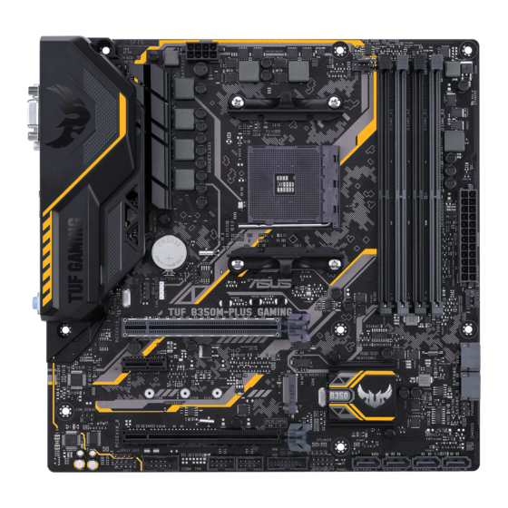
Asus TUF B350M-PLUS GAMING Посібник - Сторінка 12
Переглянути онлайн або завантажити pdf Посібник для Материнська плата Asus TUF B350M-PLUS GAMING. Asus TUF B350M-PLUS GAMING 35 сторінок.
Також для Asus TUF B350M-PLUS GAMING: Посібник із швидкого старту (2 сторінок)

7.
Clear RTC RAM (2-pin CLRTC)
This header allows you to clear the Real Time Clock (RTC) RAM in CMOS. You can
clear the CMOS memory of date, and system setup parameters by erasing the CMOS
RTC RAM data. The onboard button cell battery powers the RAM data in CMOS, which
include system setup information such as system passwords.
To erase the RTC RAM:
1.
Turn OFF the computer and unplug the power cord.
2.
Use a metal object such as a screwdriver to short the two pins.
3.
Plug the power cord and turn ON the computer.
4.
Hold down the <Del> key during the boot process and enter BIOS
setup to re-enter data.
If the steps above do not help, remove the onboard battery and short the two pins again to
clear the CMOS RTC RAM data. After clearing the CMOS, reinstall the battery.
8.
System panel connector (10-15 pin PANEL)
This connector supports several chassis-mounted functions.
•
System power LED (2-pin PWR_LED)
This 2-pin connector is for the system power LED. Connect the
chassis power LED cable to this connector. The system power LED
lights up when you turn on the system power, and blinks when the
system is in sleep mode.
•
Hard disk drive activity LED (2-pin HDD_LED)
This 2-pin connector is for the HDD Activity LED. Connect the HDD
Activity LED cable to this connector. The HDD LED lights up or
flashes when data is read from or written to the HDD.
•
ATX power button/soft-off button (2-pin PWR_BTN)
This connector is for the system power button.
•
Reset button (2-pin RESET)
This 2-pin connector is for the chassis-mounted reset button for system reboot without
turning off the system power.
9.
Speaker connector (4-pin SPEAKER)
The 4-pin connector is for the chassis-mounted system warning speaker.
The speaker allows you hear system beeps and warnings.
1-4
CLRTC
PIN 1
F_PANEL
+PWR LED
PIN 1
+HDD_LED
SPEAKER
PIN 1
Chapter 1: Product introduction
PWR BTN
RESET
