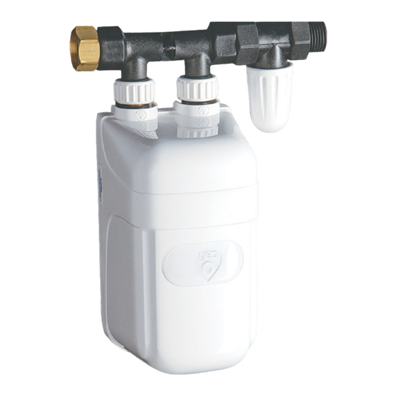
dafi IPX5 Інструкція з експлуатації Посібник з експлуатації - Сторінка 8
Переглянути онлайн або завантажити pdf Інструкція з експлуатації Посібник з експлуатації для Водонагрівач dafi IPX5. dafi IPX5 13 сторінок. Electric a flow heater with an open outlet water
Також для dafi IPX5: Інструкція з кріплення та використання (12 сторінок)

It is recommended to clean the aerator of the limescale regularly in
order to unblock it.
The cleaning of the aerator is very simple - it consists in "pushing out" the
limescale by pushing in the rubber inset of the aerator (fig. 14). In order to
extend the life of the heater, there is a filtering sieve placed in the left stub
pipe of the tap. An excessive increase in the water temperature, a significant
decrease in the water outflow or lack of outflow may mean the necessity to
clean the filtering sieve or to replace it.
It is recommended to install the DAFI mechanical water filter upstre-
am the DAFI heater
9. Instructions regarding connection to the wiring grid by means of
the DAFI junction box (available as the additional equipment)
The heaters with the power of 3,7 kW, in accordance with the change intro-
duced into EN 60335-2-35/A1:2007, may be connected to power supply,
using the non-disconnectable power cable with a socket. Other heaters
should be connected on a permanent basis to the wiring system. For such
a connection, we can use the DAFI junction box (fig. 15, fig. 16, fig. 17 and
fig. 18).
a) Insert the body of the junction box (1) into the standard flushed box for the
auxiliary electrical equipment (2) in accordance with the markings on the box
(3), then push it so that the body seal (4) could press against the wall on its
whole circumference and fix it by means of expansion bolts and screws (5) (a
section without a seal at the bottom of the body (6)
must remain unsealed, it serves the purpose of di-
scharging the possibly collecting moisture) (fig. 15.).
b) Connect the heater wire (7) with the wires of the
system (8) using the terminal block (9), fix the wire
by means of the wire contact (10) and screws (11),
push in the terminal block with the connected and
fixed wire into the socket (12) in the body of the box
(fig. 18). Please pay particular attention to the pro-
per connection of the earthing wire and to provision
fig 14
of the proper electrical connection by strong and solid tighte-
ning of the terminals.
c) Place the box cover (13) Slide the cover onto the box from the bottom,
along the heater wire until the bottom hitches (14) of the cover are slid in
under the body of the box, then press the cover strongly to the body making
sure that the dowels in the cover (15) are
slid into openings (16) in the body of the
box (fig. 17).
d) In order to remove the cover, slide in
the slot head screwdriver (17) into the side
gap between the boxy of the box (1) and
the cover (13), and turn it by 90o. (fig.18)
NOTE: In the case of failure to purchase
fig 15
