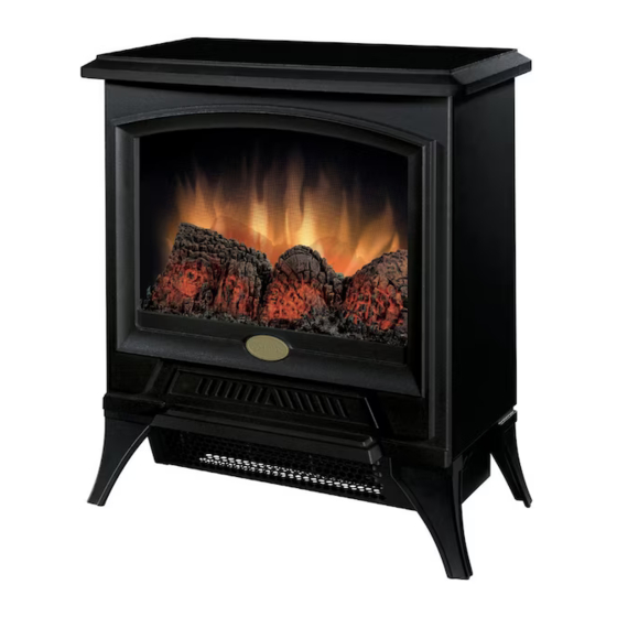
Electralog CS1205 Посібник користувача - Сторінка 5
Переглянути онлайн або завантажити pdf Посібник користувача для Піч Electralog CS1205. Electralog CS1205 9 сторінок. Sub-compact stove

NOTE
A 15 Amp, 120 Volt alternating current (VAC) circuit is required. A dedicated circuit is preferred but not
essential in all cases. A dedicated circuit will be required if, after installation, the circuit breaker trips or
blows fuses on a regular basis when the heater is operating. Additional appliances on the same circuit
may exceed the current rating of the circuit breaker.
WARNING
Ensure the power cord is not installed so that it is pinched or against a sharp edge and ensure that the
power cord is stored or secured to avoid tripping or snagging to reduce the risk of fire, electric shock or
injury to persons.
Construction and electrical wiring must comply with local building codes and other applicable regulations to
reduce the risk of fire, electric shock and injury to persons.
Do not attempt to wire your own new outlets or circuits. To reduce the risk of fire, electric shock or injury to
persons, always use a licensed electrician.
SUB-COMPACT STOVE INSTALLATION
1. Make sure the unit's MAIN ON/OFF switch is switched OFF (refer to operating instruction section).
2. Plug the unit into a 15 Amp/120 VAC outlet. If the cord does not reach, you may use an extension
cord rated for a minimum of 1875 Watts.
OPERATION
The controls are located on the right side of the heater pan. (FIGURE 2)
A. MAIN ON/OFF SWITCH
The ON/OFF switch supplies power to all unit functions (heat/flame)
B. LOW HEAT SWITCH
The LOW HEAT ON/OFF SWITCH supplies power to the heater fan and the heater element.
When the switch is in the ON position the heater operates on LOW.
C. HIGH HEAT SWITCH
The HIGH HEAT ON/OFF SWITCH supplies power to the heater fan and the heater element,
when the switch is in the ON position the heater operates on HIGH. The LOW HEAT ON/OFF
SWITCH must also be in the ON position for the high heat setting to operate.
FIGURE 2
C
B
A
3
