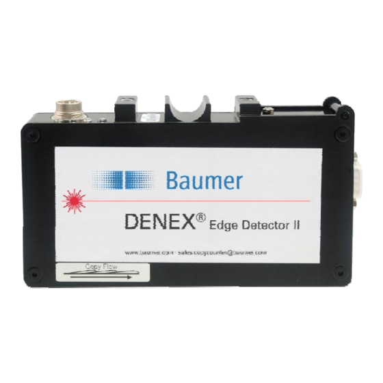
Baumer DENEX Edge Detector II Посібник користувача - Сторінка 6
Переглянути онлайн або завантажити pdf Посібник користувача для Аксесуари Baumer DENEX Edge Detector II. Baumer DENEX Edge Detector II 20 сторінок.

keeps an eye on your
DENEX
DE NEX Systems T ec hnology AB Solkraftsvägen 3 1, S-135 70 Stockholm, Sweden
Tel : + 46 (8) 7 12 00 20 Fax: + 46 (8) 712 59 4 5 E- mail: [email protected]
Figure 3.2.2 Mechanical mounting with reference surface.
3.3
Electrical installation
The interface to the copy sensor is a 7-pin connector with the following pin-out:
Matching connector: Amphenol Tuchel T3476 001, delivered with the sensor.
Pin 1 :
+24VDC in
Pin 2 :
+ Output (collector)
Pin 3 :
Not connected
Pin 4 :
Not connected
Pin 5 :
- Output (emitter)
Pin 6 :
0V
Pin 7 :
No function
3.3.1 Power Connection
Proper wiring techniques are essential for successful system installation. To reduce the
effects of electrical noise interference and static discharge, the procedures outlined in this
section must be strictly followed.
The sensor shall be connected to 24 VDC regulated power.
It must be free from transients!
Never connect or disconnect any cables when the power is on!
The normal current consumption is 150 mA.
3.3.2 Output Signal
The output is a normally open, opto-isolated transistor. Every output pulse is signaled as a
closing of the output for a certain time; see also "DIP-Switch Settings"
The specification for the output opto-coupler is as follows:
Max load current:
Max voltage:
User Manual DENEX Edge Detector II
Version 2013-02, V1.6
DENEX
DEN E X
pr oducti on
R
Laser CopySensor™
SYST EM S
TEC HN O LO G Y
Edge Detector II
100 mA
35VDC
www.baumer.com
6/20
Baumer Electric AG
Frauenfeld, Switzerland
