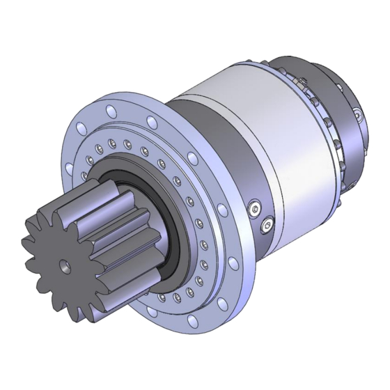
Dover TWG 250PR Посібник з обслуговування та ремонту - Сторінка 12
Переглянути онлайн або завантажити pdf Посібник з обслуговування та ремонту для Промислове обладнання Dover TWG 250PR. Dover TWG 250PR 19 сторінок.

SERVICING THE BEARING AND PINION SECTION
1.
Remove the gearbox from the vehicle by removing the bolts in the mounting flange (Item 9).
2.
Remove the brake sub-assembly, gear sets (Items 10 and 11), and ring gear (Item 12) from
unit by removing the twenty ring gear bolts and washers (Items 15 and 53). Note or mark the
orientation of the brake housing in relation to the gearbox oil drain port located in the bearing
housing (Item 1) for re-assembly.
3.
Pry the oil seal (Item 42) out of the bearing housing (item 1) and using tin snips cut the seal
and remove it from the output pinion gear (Item 2).
4.
Remove the retaining ring (Item 7) from the bearing housing (Item 1).
5.
Next secure the bearing housing assembly and press the pinion gear (Item 2), spherical bearing
(Item 4), retaining ring (Item 8) and spacer (Item 6) out of the bearing housing (Item 1).
6.
Remove the retaining ring (Item 7) from bearing housing.
7.
Tap or press the ball bearing (Item 5) out of the bearing housing.
8.
Clean and inspect all parts and hardware for damage or wear and replace if necessary.
9.
For re-assembly of the bearing and pinion section the distance of the mounting flange to the
end of the pinion must be maintained while pressing the new bearings into the housing. For this
unit this dimension is 7.750". See Image below for reference.
10.
Install outboard retaining ring (Item 7) into bearing housing.
11.
Install new oil seal (Item 42) into bearing housing (item 1).
12.
Carefully place bearing housing ass'y onto pinion shaft
making sure to have the appropriate spacers in place to
achieve the 7.750" dim. shown in this illustration.
13.
Using appropriate press tooling install and press the
spherical roller bearing (Item 4) into the housing.
14.
Install retaining ring (Item 8) onto pinion shaft making
sure it is seated properly in groove.
15.
Next insert bearing spacer (Item 6) into housing.
16.
Using proper press tooling press the ball bearing (Item 5)
into the housing.
17.
Install inboard retaining ring (Item 7) into the housing.
18.
Check sub-assembly to ensure the pinion rotates freely.
12
