Advanced Axis AX Series Посібник з монтажу та експлуатації - Сторінка 11
Переглянути онлайн або завантажити pdf Посібник з монтажу та експлуатації для Блок управління Advanced Axis AX Series. Advanced Axis AX Series 18 сторінок. Conventional zone module

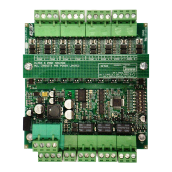
2.4.3 AX-CZM 24 VDC Power Wiring
1. Wire, in conduit, 24 VDC from the Host FACP or an ANSI/UL Listed power supply to terminals 0V and
24V of the AX-CZM module [0V = negative, 24V = positive] (see figure 10). If supplying voltage to
multiple AX-CZM modules, wire 0V and 24V to next AX-CZM module.
Note: Loss of 24 VDC will transfer the failsafe (inverted) trouble relay contact. If supervision of the failsafe
(inverted) trouble relay contact is not made by the HOST fire alarm control panel, Host panel and the
interface wiring must be installed in conduit, within the same room and no further than 20 feet away from
the AX-CZM module.
2.4.4 AX-CZM Reset Input Wiring
1. Wire, in conduit, a normal open reset relay contact, which momentarily closes on host panel reset, to
the "I/P – MON" input of the AX-CZM module. When activated (closed momentarily) the AX-CZM
module will reset all active (latched) zones (see figure 11).
Note: The HOST FACP normally open (momentary closed for reset) input is unsupervised, reset contact
and wiring must be installed in conduit, within the same room and no further than 20 feet away from the AX-
CZM module.
www.advancedco.com
www.advancedco.com
Figure 10 – AX-CZM 24 VDC Wiring
Figure 11 – AX-CZM Reset Input Wiring
11
