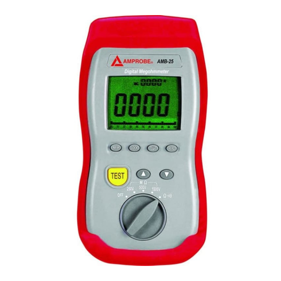
Amprobe AMB-25 Інструкція з експлуатації - Сторінка 5
Переглянути онлайн або завантажити pdf Інструкція з експлуатації для Випробувальне обладнання Amprobe AMB-25. Amprobe AMB-25 9 сторінок. Insulation tester

7
4-5 Manual Data Memory and Read Mode :
1). Clear the manual memorized data
Set the function switch to OFF position to turn off the meter.
Press and hold down "MEM" key, and turn on the meter.
When LCD shows "dEL" which means the manual memorized
data is erased.
2). Manual data memory
Press "MEM" key each time, one set of reading to will be
stored to the memory. At this moment, LCD will show the
"MEM" mark and the memory address number. Total memory
size is 9 sets.
When the memory is full, LCD will show " 9 " memory address
number.
3). Read Manual memory data
Press "READ" key to enter READ mode, the LCD will show
"READ" mark and the memory address number.
Press "
" or "
" key to select the desired memory address
number data for display.
Press " READ " key again to exit this mode.
8
5. Ω
RESISTANCE AND CONTINUITY MEASUREMENTS
1). Set the function switch to Ω
position.
2). Connect red test lead to " VΩ " terminal and black test lead to
" COM " terminal.
3). Connect the probe to the circuit to be measured.
voltage first to ensure that no haszardous voltage is present, then
switch to ohms.
4). Read the resistance value from the display. If the resistance is
approximately 40Ω or less, the meter will beep.
6. MΩ INSULATION RESISTANCE MEASUREMENTS
6-1 Measuring Insulation Resistance
Measuring insulation resistance requires the application of
potentially dangerous voltage to the circuit.
exposed bonded metal work.
Before proceeding, ensure that the installation is correctly wired
and no personnel are endangered by any test.
1). Set the function switch to the desired MΩ test voltage position.
2). Connect red test lead to " VΩ " terminal and black test lead to
" COM " terminal.
3). The display will show "-----" until the TEST button is pushed.
Press and hold the TEST key. The upper right display shows
the test voltage applied to the circuit under test. The main
display shows the resistance until a stable resistance reading is
displayed on the main display.
Measure
This may include
