DPS Telecom Net Dog 82 IP Посібник з експлуатації - Сторінка 2
Переглянути онлайн або завантажити pdf Посібник з експлуатації для Мережеве обладнання DPS Telecom Net Dog 82 IP. DPS Telecom Net Dog 82 IP 12 сторінок.
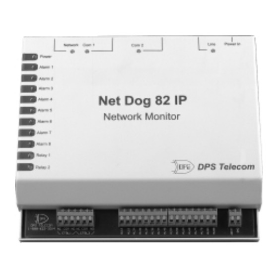
Fig. 2 - Net Dog monitors Ethernet device status and interfaces discrete
Applications
The illustration above shows how the Net Dog fits
into a typical network site.
Net Dog's eight fault alarm inputs accept any contact
closure type of event notification, such as door switches,
fuse alarms, major and minor equipment alarms, high
temperature alarms and tower light monitors.
There are 2 control relay outputs for operating stand-
by equipment, door locks or emergency lighting.
The ASCII port can be connected to the craft port of
any serial device (i.e. server, radio, or PBX). The craft
port can then be accessed using Telnet via LAN/WAN.
This port is also used to configure the Net Dog.
The Ethernet port is used to contact other devices
and determine their viability by "pinging." If a given
device does not respond, it is reported as off line.
The line port is a modem interface to a telephone
line. The modem operates at 1200, 2400 or 9600 baud
options. When Net Dog has an event to report, it uses
this port to dial out to a paging terminal or to a DPS ele-
ment manager, such as T/MonXM or the IAM. This port
may also be used to configure the Net Dog.
Installation
1. Alarm inputs can be individually changed to inter-
face a TTL alarm source by moving jumpers on the
PC board. The alarm inputs are set by factory
default for dry contact alarm sources (jumpers A +
C). (See Fig. 3 for a schematic representation of the
input configurations.)
D-PC-295-10A-0V
May 5, 2000
fault points and controls at your network sites.
2
A. To change an input for TTL, remove the six
screws on the sides of the case and lift off the
cover.
B. Locate the jumper area in the bottom right area
of the circuit board. Refer to Fig. 5 to determine
which vertical row of jumpers belong to the
alarm channels you are changing.
C. Change jumpers for TTL externally or internally
biased, according to your application needs, as
in Fig. 4.
D. Replace the cover when finished changing
jumpers.
2. Use the mounting template to position the mounting
hardware, then mount the Net Dog in place.
3. Connect alarm and control leads per Fig. 6. The con-
trol point outputs can be wired for normally closed
or normally open contacts.
5. Connect data lines per Fig. 7.
6. Connect power. If using AC adapter, connect adapter
to the Net Dog before plugging into AC. If using a
battery supply, connect to the DC power terminals
(See Fig. 6).
7. Configure the Net Dog as outlined in the Software
Configuration section on page 4.
8. Test the Net Dog for proper operation per Table L.
9. In case of difficulty, contact DPS Tech Support at
(800) 622-3314.
OG113939.001