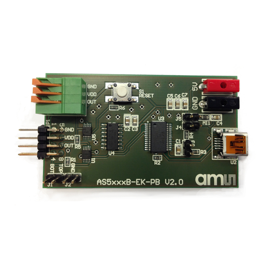
AMS AS5 Series Посібник користувача - Сторінка 6
Переглянути онлайн або завантажити pdf Посібник користувача для Адаптер AMS AS5 Series. AMS AS5 Series 12 сторінок. Uart programmer
Також для AMS AS5 Series: Посібник з експлуатації (11 сторінок)

3
Adapter Board and Pinout
Figure 5:
Adapter Board Pinout
Figure 7:
Pinout Description
Pin# Board
P1 - 1
P1 - 2
P1 - 3
P1 - 4
P1 - 5
P1 - 6
P1 - 7
P1 - 8
P1 - 9
P1 - 10
P1 - 11
P1 - 12
P1 - 13
P1 - 14
P1 - 15
P1 - 16
Demo Kit Manual • PUBLIC
UG000401 • v1-00 • 2018-Oct-31
Document Feedback
5V
3V3
GN D
C S n
CL K
MOSI
MISO
GN D
B
A
I/PW M
GN D
GN D
W/PW M
V
U
AS 5x47 U
Pin# AS5X47U
Symbol Board
11
5V
12
3V3
13
GND
1
CSn
2
CLK
4
MOSI
3
MISO
13
GND
6
B
7
A
14
I/PWM
13
GND
13
GND
8
W/PWM
9
V
10
U
Figure 6:
Sensor Pinout
CSn
1 1
CLK
2
MISO
3
MOSI
4
TEST
5
B
6
A
7
Type
Description
Power supply
Positive supply voltage
Power supply
3.3V LDO output
Power supply
Ground
Digital input
SPI chip select (active low)
Digital input
SPI clock
Digital input
SPI MOSI
Digital output
SPI MISO
Power supply
Ground
Digital output
Incremental signal B (quadrature)
Digital output
Incremental signal A (quadrature)
Digital output
Incremental signal I (index) or PWM
Power supply
Ground
Power supply
Ground
Digital output
Commutation signal W or PWM
Digital output
Commutation signal V
Digital output
Commutation signal U
AS5x47U Adapter Board
Adapter Board and Pinout
14
I/PWM
GND
13
VDD3V
12
VDD
11
U
10
V
9
W/PWM
8
│ 6
12
