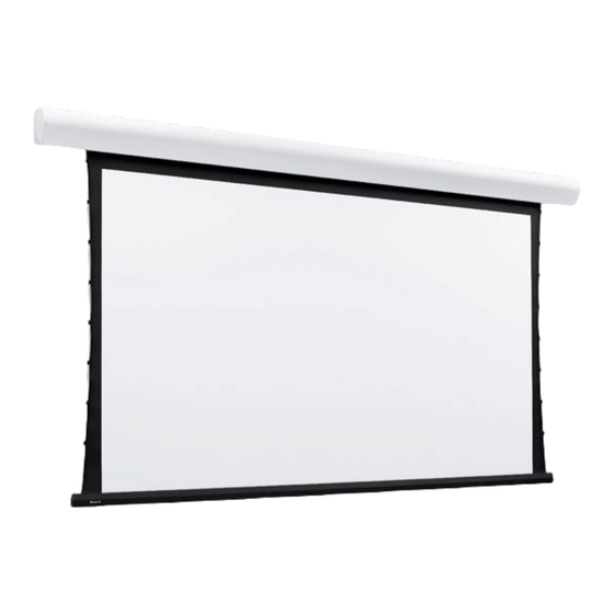
Envoy by Draper
13
7
/
"
16
9
7
/
"
16
1
4
/
"
1
16
/
"
8
9
7
/
"
16
Standard
Offset
Construction
Construction
Single Station Control
Junction box at
left end of screen
To 115V Line
Control
Switches
24 VDC
STOP
STOP
If you encounter any difficulties installing or servicing
your Envoy screen, call your dealer or Draper, Inc.,
Spiceland, Indiana, (765) 987-7999, fax (765) 987-
Case Dimensions/Method of Installation
Incl. mtg.
brackets
Support rods
by others
2¼"
5
/
"
Mounting
8
brackets
Surrounding
ceiling
1¼"
Conduit connection
2" up on this end
Wiring Diagrams
Internal Screen Wiring
White (Common)
Black (Down)
Red (Up)
Green (Ground)
Dashed wiring
by installer
Single gang box by others
Control
Min. 4" x 2 1/8" x 1 7/8" deep
switch
Blue
Red
Black
Location of key
operated on-off
switch if furnished
Low Voltage (& Wireless) Control Wiring Diagram
Low Voltage Control Module
Black
Black (DN)
Black (DN)
Red (UP)
Red (UP)
Red
White (COM)
White (COM)
White
Black (DN)
Red (UP)
Optional Infrared
White (COM)
Receiver Package
Optional
Radio
Receiver
Package
Fabric Width + 15"
2"
Viewing
7½"
surface
Multiple Station Control
Junction box at
left end of screen
Internal Screen Wiring
White (Common)
Black (Down)
Motor
Red (Up)
Green (Ground)
Cap off with wire
nut and tape
Red
Blue
Black
Red
Blue
Black
Blue
Red
Black
Location of key
operated on-off
switch if furnished
To 110-120v Line
White
Red
Brown
Black
Yellow
Green
Dotted wiring by installer
Location of key
operated on-off
switch if furnished
To 110-120V Line
Ceiling
closure door
Ceiling grid and
tile (by others)
Motor
Dashed wiring
by installer
Single gang box by others
Min. 4" x 2 1/8" x 1 7/8" deep.
3 shown. More or less equally
feasible.
Internal Screen Wiring
White (Common)
Red (Up)
Black (Down)
Green (Ground)
Page 2 of 2
2"
9
7
/
"
16
3¼"

