Carlin 48245 Посібник
Переглянути онлайн або завантажити pdf Посібник для Системи управління Carlin 48245. Carlin 48245 4 сторінки. Smart ignition – cad cell oil primary control
Power input (from limit circuit)
Motor load
Ignitor load
Operating temperature limits
Installing and Wiring
48245 control must be installed and serviced only by a qualified service technician.
1. Always disconnect power source before wiring to avoid electrical shock or damage to the control. All wiring must comply with
applicable codes and ordinances.
2. Thermostat terminals (T-T) provide a current source. Never apply external power to these terminals under any circumstances.
Mounting
• The control may be mounted on a 4" x 4" junction box in any convenient location on the burner, furnace or wall. The location
must not exceed the ambient temperature limit, 140°F.
Wiring
• Wiring must comply with local and national electrical codes, and with the wiring diagram.
• Individual or bundled neutrals may be attached to any L2 terminal.
Field checks
1. Select preferred TFI by 1) leave jumper in for 45 seconds or 2) remove jumper for 15 seconds. IMPORTANT: TFI change oc-
curs on next call for heat.
2. Safety timing (TFI) test – Remove one CAD cell wire (F-F). Start burner. The control should lockout within the TFI time limit.
Replace CAD cell wire.
3. Flame failure test – Start burner. After flame is established (after TFI period), close the oil supply hand valve. This will cause a
flame failure sequence as described in the Startup & Operation section of this data sheet. Under recycle, please read "Smart
Ignition" on page 3.
4. If control does not operate as described, check the wiring.
Startup & Operation
Three wire or four wire configuration
• See Figure 1 for wiring diagram for four-wire configuration
(Smart Ignition)
• See Figure 2 for wiring diagram for three-wire configuration
Do not start the burner if the combustion chamber contains oil or oil vapor.
Per UL requirements, the control will not turn on if the CAD cell senses flame during the self-test. If the CAD cell sees
light (flame) at the beginning of a cycle, the control will remain in self-test mode until the CAD cell no longer senses light (flame).
The amber LED will blink momentarily
Tech Support (800) 989-2275
• Intermittent Duty when you need it,
Ignitor-saving Interrupted Duty when
you don't
• Oil Pump Bleed Assist
• Recycle on Flame Failure
• Diagnostic LEDs
Status, lockout, flame
120 VAC, 60 HZ
10 FLA / 60 LRA
120 VAC, 60 HZ, 500 VA
+32°F to +140°F
every 3 to 4 seconds and green LED will be on or flashing.
SEE WIRING DIAGRAM ON NEXT PAGE
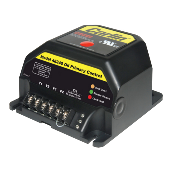
Model 48245 with Smart
Ignition – CAD Cell Oil
Primary Control Data Sheet
• 45 or 15 second TFI
• Increased Flame Accuracy
• Thermostat/Aquastat Compatible
60 seconds
• Improved SMC Technology
zero bleed voltage during standby
• Works Well with Generators
Insensitive to frequency changes
Storage temperature limits
Thermostat anticipator current
CAD cell resistance (with flame)
Agencies
Model 48245 Diagnostic LEDs
– Amber OFF
– Green OFF
– Red OFF
www.carlincombustion.com
-40°F to +185°F
0.1 A, AC
R < 1500 OHMS
UL recognized (US & Canada)
– Amber ON
– Amber FLASHING
– Green ON
– Green FLASHING
– Red ON
– Red FLASHING