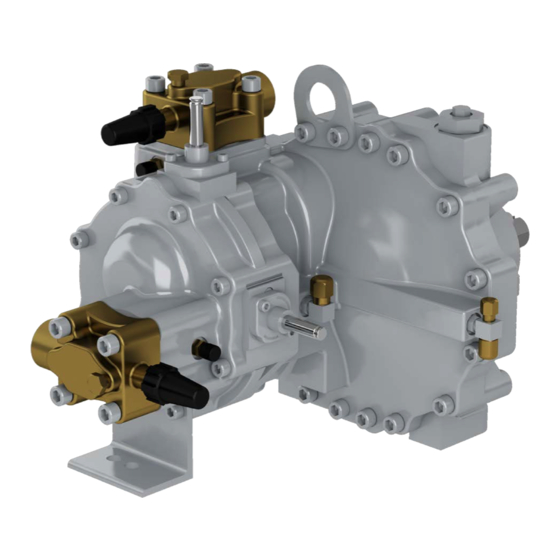
Carlyle 06T Посібник із застосування - Сторінка 16
Переглянути онлайн або завантажити pdf Посібник із застосування для Повітряний компресор Carlyle 06T. Carlyle 06T 20 сторінок. Screw compressor

5.2 Overcurrent Protection
06T screw compressors must be protected with a three-
phase manual-reset type of overcurrent protection.
The code agency certifications of the 06T compressor is
contingent upon the use of appropriate overcurrent protec-
tion. Properly selected overcurrent devices protect the com-
pressors against running overcurrent, locked rotor, as well
as primary and secondary single phasing faults.
Overcurrent protection must comply with the following:
•
Manual Reset
•
The device must trip at or below the maximum MCC
listed for the compressor. Settable devices may re-
quire settings that differ from the maximum allowed
current. Consult the manufacturer's documentation
for proper setting of these devices.
•
To minimize nuisance tripping risks, the maximum ra-
tio between the must trip and must hold values can-
not be larger than 1.15
•
Locked Rotor Trip Timing:
a. Across-the-Line Start: Device must trip in 2 to 6
seconds
b. Part Wind Start: Device must trip the first three con-
nected legs in 2 to 6 seconds and the remaining
three connected legs in 1 to 3 seconds
06TR LOW TEMP COMPRESSORS
COMPRESSOR
CONTINUOUS
HP
MODEL
06TRC033F2EA
15
06TRD039F2EA
20
06TRD044F2EA
20
06TRE048F2EA
25
06TRE054F2EA
25
06TRF065F2EA
30
06TRG078F2EA
35
06TRH088F2EA
40
06TRC033B2EA
15
06TRD039B2EA
20
06TRD044B2EA
20
06TRE048B2EA
25
06TRE054B2EA
25
06TRF065B2EA
30
06TRG078B2EA
35
06TRH088B2EA
40
06TRK108B2EA
50
06TRC033C2EA
15
06TRD039C2EA
20
06TRD044C2EA
20
06TRE048C2EA
25
06TRE054C2EA
25
06TRF065C2EA
30
06TRG078C2EA
35
06TRH088C2EA
40
16
MAXIMUM
LOCKED
ROTOR
CURRENT
CURRENT
90
286
104
348
104
348
128
433
128
433
154
611
181
721
203
825
46
142
49
173
49
173
64
215
64
215
76
253
89
323
101
370
114
440
33.5
114
39
138
39
138
53
172
53
172
62
219
72
258
81
296
The 06T compressor motor may be protected using a rec-
ognized variable speed drive that meets these compressor
protection requirements. The system designer is responsi-
ble to program these requirements appropriately.
For part wind start applications Carlyle recommends a 1 to
1.25 second time delay between energizing the first and
second legs.
If the end user is not intending on using the full published
operating envelope; the overcurrent protection can be sized
to trip at lower values than the maximum MCC.
5.3 Allowable Voltage Range
The allowable voltage variation at the compressor terminals
for the 06T screw compressors is shown in the table below.
Model #
Nominal Voltage
Digit 9
B
C
F
06TA MED/HIGH TEMP COMPRESSORS
COMPRESSOR
VOLTAGE
MODEL
06TAD033F2EA
06TAE038F2EA
06TAF044F2EA
208/230V-3-
06TAF048F2EA
60Hz
06TAG054F2EA
200V-3-50Hz
06TAG065F2EA
06TAH078F2EA
06TAK088F2EA
06TAD033B2EA
06TAE038B2EA
06TAF044B2EA
06TAF048B2EA
460V-3-60Hz
06TAG054B2EA
400V-3-50Hz
06TAG065B2EA
06TAH078B2EA
06TAK088B2EA
—
06TAD033C2EA
06TAE038C2EA
06TAF044C2EA
06TAF048C2EA
575V-3-60Hz
06TAG054C2EA
06TAG065C2EA
06TAH078C2EA
06TAK088C2EA
Voltage Range
Min
460-3-60
396
400-3-50
342
575-3-60
495
208/230-3-60
187
200-3-50
180
MAXIMUM
CONTINUOUS
HP
CURRENT
20
104
25
128
30
163
30
163
35
182
35
181
40
203
50
230
20
49
25
64
30
76
30
76
35
88
35
89
40
101
50
114
—
—
20
39
25
53
30
62
30
62
35
78
35
72
40
81
50
92
Max
528
456
660
264
230
LOCKED
ROTOR
CURRENT
348
433
510
510
610
721
825
974
173
215
253
253
305
323
370
440
—
138
172
202
202
242
258
296
351
