CommScope FOSC-ACC-B-TRAY-12-RBN Інструкція з монтажу - Сторінка 3
Переглянути онлайн або завантажити pdf Інструкція з монтажу для Корпус CommScope FOSC-ACC-B-TRAY-12-RBN. CommScope FOSC-ACC-B-TRAY-12-RBN 6 сторінок. Fiber optic splice closure trays: a/b ribbon size
4.
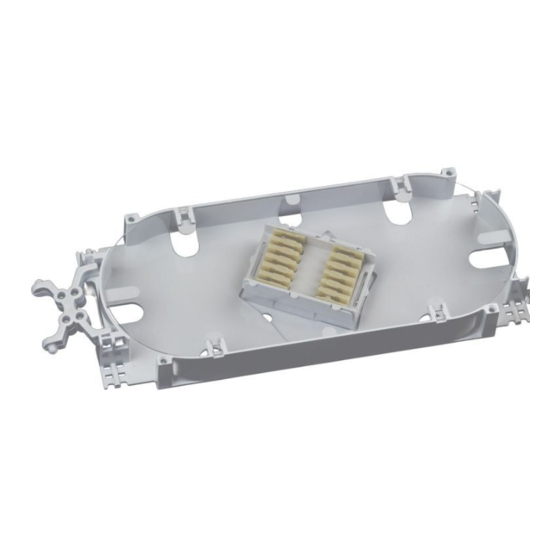
Secure prepared ribbon bundles to the splice tray with
1-1/2 wraps of loose buffer tube wrap and two tie wraps.
(Figure 2)
If using ribbon transportation tubing, see Figure 3.
5.0 Ribbon Fiber Splicing Procedure
1.
Measure the ribbon from the holes on the hinged end of
the tray. Note: All feeder lengths will be 24" and distribu-
tion lengths will be 35" for butt configurations. The
lengths for inline will always be 24" for feeder and distri-
bution lengths. Refer to the diagram on pages 4 and 5
that matches your application. Page 4 shows butt splices,
while page 5 shows inline splices.
2.
Remove the splice holder from the tray.
3.
If splicing 6 or less ribbons, remove the top splice module,
splicing the ribbon starting from the inside ribbons onto
the bottom splice module. Snap the top splice module
back into the splice hoder.
Note: If splicing 12 ribbons, fill the bottom splice module
first then the top splice module.
4.
Place a mark on the top splice module as shown in the
diagrams. This will aid in positioning the splice holder on
the tray.
5.
Turn (slowly) the splice holder in the direction of the
selected diagram (on page 4 or 5) that matches your
application. The ribbons will form into loops. Place the
splice holder in the center of the loops and snap the
holder onto the tray.
Tip: A fiber pick will make installation easier. Be careful
not to pinch the ribbons under the splice holder.
6.
Arrange the fiber loops inside the tray. Secure all ribbons
under the hold down tabs. If lengths are unequal or cut
too long, extra slack may need to be pulled back into the
storage area.
7.
Snap the tray cover into place.
Figure 2
Figure 3