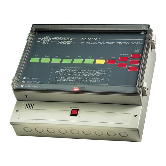
Formula Sound SENTRY MK2 Посібник користувача - Сторінка 6
Переглянути онлайн або завантажити pdf Посібник користувача для Системи управління Formula Sound SENTRY MK2. Formula Sound SENTRY MK2 11 сторінок. Environmental noise control system
Також для Formula Sound SENTRY MK2: Посібник користувача (17 сторінок)

Installation
Select and install a suitable contactor, arranging the installation to control all the power outlets in
the vicinity. (If any are left uncontrolled it will not take very long for the enterprising band or D. J. to
find and use them. It is inadvisable to arrange control of only half the outlets in a venue).
In very large installations, it is a simple matter to make 1 contactor control many others
of whatever current rating is required.
Connect the contactor control back to the Sentry using appropriate cable and connections
depending on the type of contactor used.
Connections
All connections to the Sentry are located beneath the lower removable front cover. On this cover is
also mounted the reset button which connects to the printed circuit board via a 2 pin plug and may
be easily disconnected. See Drg No 879.for more details.
Connect the Sentry to a suitable mains outlet using the terminals labelled "Mains In" and ensure
that the earth is also connected. The mains consumption is approximately 1amp at 240V - a
5amp lighting feed could be utilised. Connect via an isolating switch or removable plug socket
arrangement so that the unit can be isolated when necessary.
For use on 120V the consumption will be approximately 2amps
ENSURE THAT THE MAINS SUPPLY IS NOT THE SAME AS THAT CONTROLLED BY THE
CONTACTOR. REMEMBER THIS SUPPLY CONTROLS ALL THE POWER OUTLETS
CONTROLLED BY THE CONTACTOR.
Warning Lamp
Provision to switch a mains warning lamp to a maximum of 60VA is provided. The lamp can be of
any style considered suitable but must have a maximum consumption of 60VA (60 watts). It is
connected to the mains outlet terminals labelled "warning lamp". Alternatively a relay or contactor
may be used to switch other lamps as required. Good wiring practice should be observed.
Remote Reset
Provision for a remote reset button is provided and if this facility is required a momentary action
push button or key switch should be fitted. Site this in a Manager's office or suitable location.
(See separate drawing (Drg No 879) giving full connection details).
Setting The Permissible Volume Level
Adjustment of allowable noise level is made by adjusting the pre-sets ADJ 1 and ADJ 2. These
are located beneath the removable cover at the left hand end of the unit. They are 10-turn pre-
sets to provide fine adjustment. ADJ1 sets the normal operating level, ADJ 2 sets the level for a
second threshold which can be initiated remotely. An indicator on the front panel will show when
level 2 is selected. Take care when making adjustments and use a small screw driver . Try to
make adjustments when the noise level is displayed on the bar graph meter as you will be able to
see the changes displayed on the meter.
The adjustment pre-sets have a slipping clutch at the end of travel to prevent damage. But this
can cause confusion if the pre-set is at the end of travel as it then appears to do nothing (this is
not usually a problem once you know about it).
Page 5
